
The sensitivity depends on the transistors used in the circuit. For the pair BD135/136, motors up to 1 A can be controlled. The gain of the transistor makes control possible from currents sources of about 5 mA or less.
Using the TIP31 and TIP32, since the gain is lower, you’ll need more current to control a 1 A motor. In some cases, the resistor value must be reduced to 470 Ω. We suggest that the reader experiment with the resistor to find the best value for the application.
For an applications as shield the values are ideal and the power supply can be separated for the microcontroller.
The indicated values (1 kΩ for R1 and R2) are suitable when the signal source is a TTL or CMOS logic circuit.
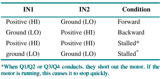
The following table gives the control logic for this block:
The tables given in the previous articles in this site are valid when using the NPN and PNP transistor, according to the current drained by the motor. Depending on the motor, a capacitor also is needed in parallel, and the transistor must be altered to achieve the correct operation.


