* Remember that constant voltage sources here are the batteries normally used to power the robots and other appliances. These are different from the current sources. Some constant voltage sources are described in other parts of this book.

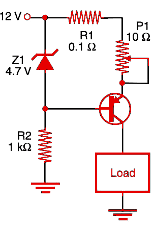
The zener diode is a 400 mW or 1 W type, and P1 is used to adjust the current across the load. This circuit can be used to maintain constant currents up to 500 mA. If larger currents are involved, a Darlington transistor can be used.
P1 must be a wire-wound potentiometer, and its dissipation rate is important if larger loads are controlled. The current adjustment can be made using a current meter in series with the load.
If higher voltages are used at the input, the 1 kΩ resistor must be increased in value, and the zener must have larger dissipation power. If the load is a motor, it is convenient to add a decoupling capacitor in parallel. Electrolytic capacitors between 1 and 470 ?F are recommended for this task.


