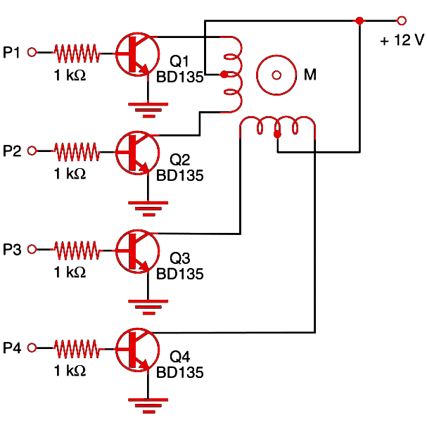
The sequence of pulses to position the motor is applied to the inputs P1 to P4 for an appropriate translator (see the following blocks). The circuit needs about 12 mA per input to drive a 500 mA motor, making it compatible with TTL or CMOS logic.
The transistors can be replaced with powerful units. If low-gain transistors are used, you’ll probably need more current in the input. The next block, using Darlington transistors, can be important if high-power stepper motors are used. The transistors must be mounted on heat sinks.


