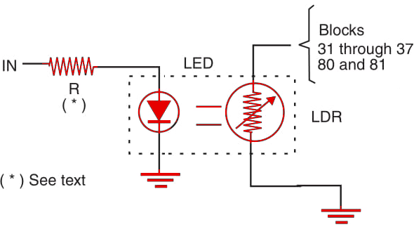
The LED and the LDR must be installed inside an opaque enclosure to avoid the influence of ambient light. Remember that the resistance of the LDR falls when the input logic level is high (1).

Figure 1 - Opto-isolator for TTL logic.

Note: Complete devices using LEDs as emitters, and devices such as Schmitt triggers, SCRs, transistors, Darlington transistors as receivers, and other configurations can be designed.


