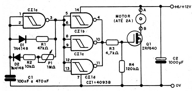
The other three gates are wired as a buffer/amplifier to drive the output transistor.
Capacitor C1 determines the frequency range and must be chosen to suit the motor. In some cases, some motor vibration can occur if an improper capacitor is used.
Resistor R1 determines the smallest pulse width applied to the motor. and the ratio between P1 and R2 sets the maximum duty cycle of the control.
Experiments with R1 and R2 must be conducted to find the best operating range for any motor.
D1 and D2 can be any general-purpose silicon diode such as the 1N914,1N4148, or even 1N4002.
Pin 1 of the IC can be used as an external enable input. The circuit can be used with Darlington transistor if you replace R3 with a 4.7 k Ω resistor.
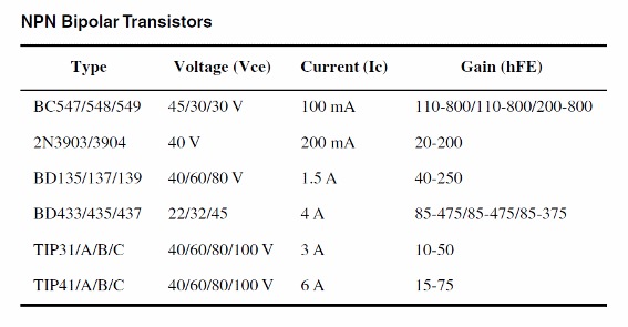
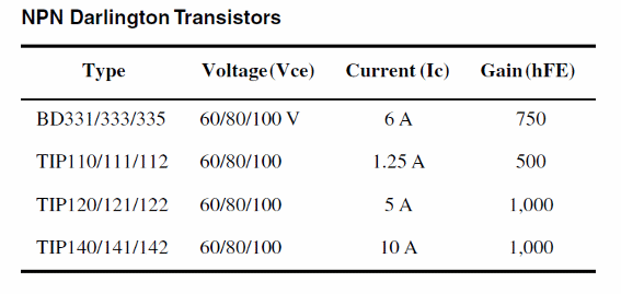
Figure 1 shows the schematic diagram for this project.
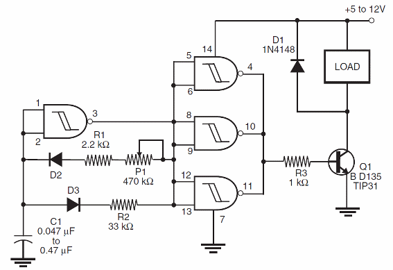
Figure 2 shows a version for this circuit using a power MOSFET.
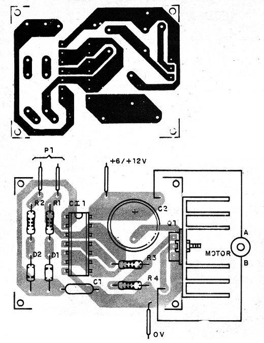
A printed circuit board is shown by figure 3. Take care with the position of the transistor, since according the type the terminal can change their positions.
