

Functional Diagram and/or Package:
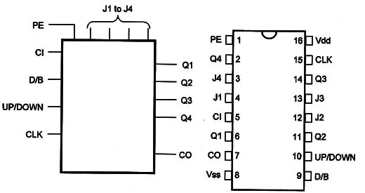
Pin Names
Vdd - Positive Supply Voltage [3V to 15V]
Vss - Ground
CLK - Clock
Q1, Q2, G3, Q4 - Outputs
J1, .J2, J3, J4 - JAM Inputs
PE - Preset Enable
Cl - Gerry ln
CO - Carry Dut
UP/DOWN - Up-Down Selection
D/B - Decede/ Binary Selection
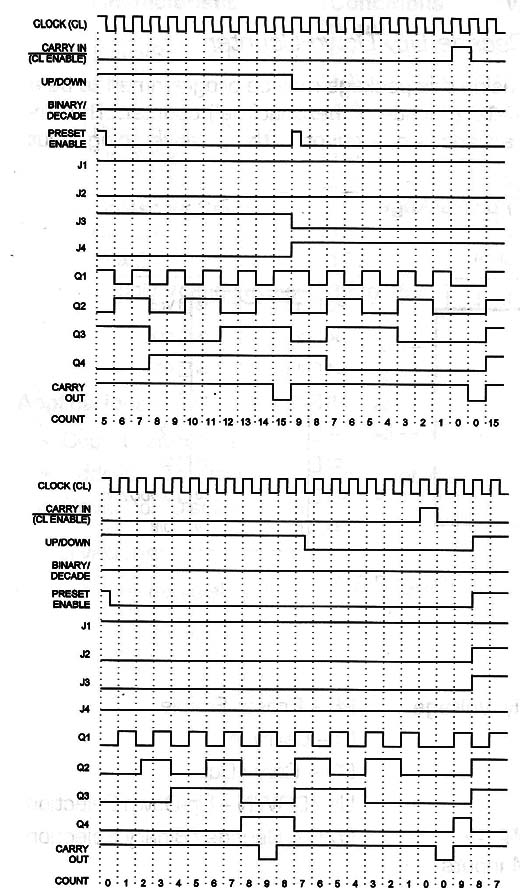
Operation Mode:
-
LD and EN are grounded.
-
With D/B With a “0” logic level, the circuit counts by tens. If in the “'1” logic level the circuit counts by sixteens.
-
If UP/DOWN is held at the “1” logic level, the circuit operates as an up counter and With the pin at the “0” logic level the circuit operates as a down counter.
-
The changes in the count occur With the positive transition of the clock.
-
CD is “0” for count 9 [bcd] and 15 [binary].
-
Em ground stops the count.
-
-
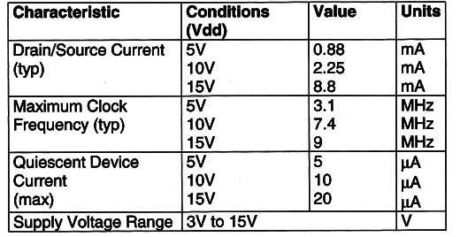
Electrical Characteristics:
-
-
- Applications:
- Programmable Binary/De-cade Counting
-
A/D and D/A Conversion
-
Up/Down Binary/Decade Counting
-
Magnitude end Sign Generators
-
Difference Counting
-
-
Observations:
- The up-down control can be changed only When the clock is at the “'1” logic level.
- Cascading: Connecting the DUT pin of the first decade to EN of the second decade, it is possible to drive the circuit from a common clock for fully synchronous operation.
-


