
Description: The two 4-input AND gates in this package can be used independently
Functional Diagram and/or Package:
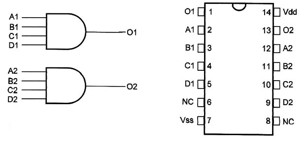
Pin Names:
Vdd - Positive Supply Voltage [3V to 15V]
Vss - Ground
A1, B1, C1, D1, A2, B2, C2, D2 - Inputs
O1, O2 - Outputs
NC - Not Connected
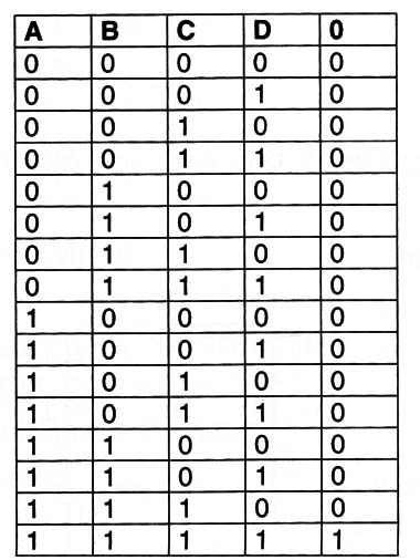
Truth Table
Operation Mode:
The gates are independent.
The logic level found in the output depends on the logic levels applied to the inputs according to the truth table.
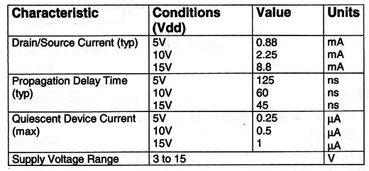
Electrical Characteristics:
Applications:
Interfacing and Drive
Digital Amplifier


