
We describe the assembly of a useful circuit tester for the reader that works with digital logic: a logic probe that can indicate whether a point in a circuit is in the high (1) or low (0) level. The circuit is extremely simple and can be powered by the circuit being tested, as long as its voltage is in the range of 3 to 15 V.
The consumption depends only on the resistors R3, R4 and R5 which determine the brightness of the LEDs. Figure 1 shows the complete circuit of the logic probe.

As we can see it is based entirely on the NAND gates of a 4001 integrated circuit.
There are three indicator LEDs which work to show when the analyzed output is at the high, low level or the applied signal is pulsating.
The assembly is very simple and can be carried out on a small printed circuit board with the arrangement of components shown in Figure 2.
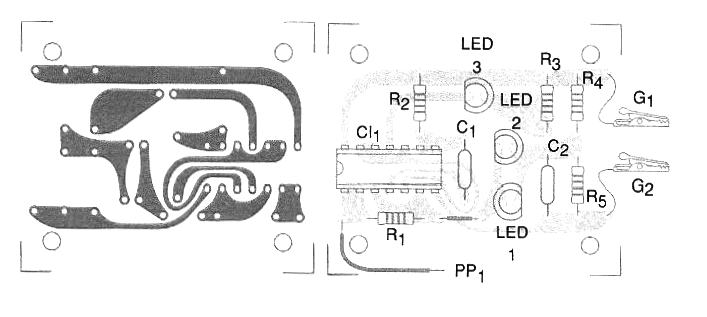
CI-1 - 4001 - CMOS integrated circuit
LED1, LED2 and LED3 - red, green and yellow LEDs.
R1 - 2.2 M ohms x 1/8 W - resistor - red, red, green
R2 - 5.6 M ohms x 1/8 W - resistor - green, blue, green
R3, R4, R5 - 2.2 k ohms x 1/8 W - resistors - red, red, red
Several:
Probe, ground clip, clip for connection to the source, mounting box, printed circuit board, wires, solder, etc.


