We describe a simple timer or timer with a common incandescent lamp that has an active CMOS integrated circuit and a Darlington transistor with easy to obtain power. With the indicated transistor, lamps up to more than 1 ampere of driving current can be controlled in both 6 and 12 volts.
However, we can also use a low-power PNP transistor like the BC558 if the lamp used is up to 50 mA or even if an LED is used.
An interesting application for this project, with little adaptation, is in determining the starting time of competitions with the use of a red and a green lamp.
The timing can be adjusted between a few seconds and several minutes using a trimpot or a common pot.
Characteristics:
Supply voltage: 6 or 12 V depending on the lamp
Resting current: 0.5 mA (tip)
Maximum charge current: 1 amp
Timing: 5 seconds to 5 minutes (approx.)
HOW IT WORKS
Two of the six inverters of a CMOS 4049 integrated circuit are used as a monostable whose time at which the output remains at the high level depends on the time at which C1 remains charged after the activation of S1.
In this way, the value of C1, plus the setting of P1 that in series with R2 determine the discharge speed, are responsible for the operating time of the monostable.
In order to have a higher drive power, the other 4 inverters are used as amplifier buffers, so that when S1 is activated, the output of these buffers goes to low level.
With the use of a PNP transistor, we then have saturation for a determined time after the activation of S1 and with this the energization of the lamp used as a load.
A double drive system, in which a green light goes out and lights a red one for a certain time, can be done as shown in figure 1.
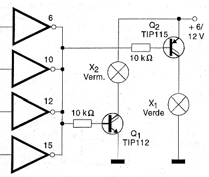
In this circuit, while the output of the buffers remains high, Q1 is in the cut and Q2 is saturated. With the output going low, after activating S1, Q1 saturates and Q2 goes to cut.
Using small power transistors, as shown in figure 2, the circuit can be used to drive common LEDs.
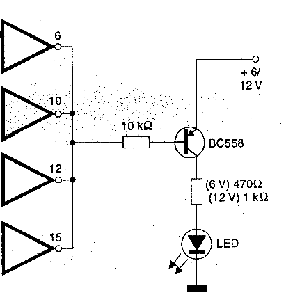
The value of c1 determines the time range that we can obtain with this circuit and values between 10 uF and 1000 uF can be used.
ASSEMBLY
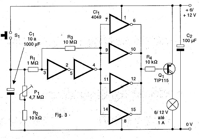
In figure 3 we have the complete diagram of the timer.
In figure 4 we have the arrangement of the components on a printed circuit board.
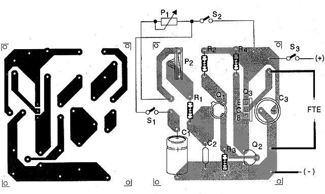
The integrated circuit should preferably be mounted in a socket. For the power transistor we need a small heat radiator. Resistors are 1/4 watt or larger and electrolytic capacitors must have a slightly higher working voltage than that used for power.
The lamp must have a voltage according to that used for power and a maximum current of 1 amp.
The lamp may be away from the plate and the trigger point. The actuation switch itself, which is of NA pressure, can be replaced by some other type of sensor actuation, such as a reed-switch.
TEST AND USE
To test the device, just feed it and activate S1 for a moment. The lamp should light up. Then set P1 to the desired timing.
Proven to work, just do the final installation.
Semiconductors:
CI-1 - 4049 - CMOS integrated circuit
Q1 - TIP115 or equivalent - Power PNP Darlington transistor
Resistors: (1/4 W, 5%)
R1 - 1 M ohm - brown, black, green
R2 - 10 M ohm - brown, black, blue
R3, R4 - 10 k ohm - brown, black, orange
P1 - 4.7 M ohm - trimpot or potentiometer
Capacitors:
C1 - 10 to 1000 uF / 12 V - electrolytic
C2 - 100 uF / 12 V - electrolytic
Several:
S1 - NA push button (normally open)
X1 - 1A lamp - 6 or 12 V
Printed circuit board, socket for integrated circuit, heat radiator for Q1, mounting box, socket for lamp, wires, solder, etc.