

Multimeters having a good sensitivity with an input resistance greater than 1MΩ, such as digital and analog even more elaborate types, they can be used to measure RF signals.
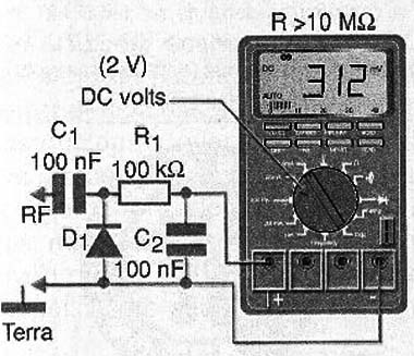
What is done is to use a simple threshold detector circuit, as shown in Figure 1, to obtain a DC voltage capable of exciting the instrument.
These circuits allow to measure voltages of a few hundred millivolts to the reverse breakdown voltage of the diode.
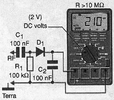
In the case of the Figure 1 circuit, we have what is called detector type "shunt" or derivation. Another way of detecting the signals for measuring purposes is through a series circuit, as shown in Figure 2.
The shunt circuit is particularly suitable for measurements at very high frequencies because it is connected directly to ground, thus facilitating the layout of any board that is used.
Of course, when working with very high frequencies is appropriate to maintain the links between components the most short as possible.
In Figure 3 we have a response curve for the case of a diode commonly used as a 1N5711 Schottly which is ideal for such applications given its lowest driving voltage.
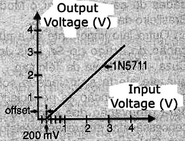
However, common germanium diodes as 1N34 or 1N60 provide excellent results up to the maximum operating frequency of these components, a few hundred Megahertz.
And in the latter case, commonly used silicon diodes like 1N4148 can also be used, but in this case should be considered an "offset" of 300 mV order. The offset of the germanium diode is only 60 mV whereas for Schottky diode will have 100mV.
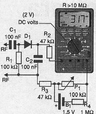
One way to correct the offset of the problem of used diodes, which can introduce errors in very weak signal measurements is with a compensating circuit, as shown in Figure 4.
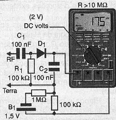
Set then the trimpot for the offset obtained is zero, as shown in the graph of Figure 5.
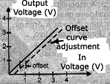
The idea of this circuit is to use a stack to generate a negative voltage, of the same order as the offset voltage of the diode being employed in detection.
Another interesting setup for measurements in RF is the differential shown in Figure 6.
To obtain a linear response to input signals, one may use an operational amplifier as the circuit shown in Figure 7.
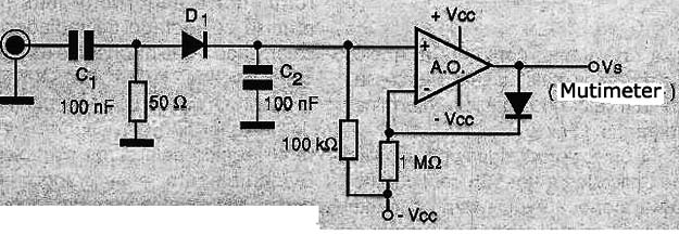
Operational amplifiers such as the LM358 may be employed in the configuration shown. This configuration also has an extra 50-ohm resistor which enables taking measurements in line with that impedance, although the circuit has not ideal wedding impedances.
Conclusion
Despite the common diodes present a characteristic that follows the square law for low intensity signals below 100 mV, additional circuits can be designed taking advantage of it.
These circuits can be used mainly when you want a good impedance matching with the signal source to perform more accurate measurements.
However, the design of such circuits is up to the readers. What we here was a small idea of how diodes of various types can help in making RF measurements with a common multimeter.


