

We’ve already covered on several articles in this website the need of using True RMS multimeters in the work with alternating current so as to avoid problems of errors in measurements.
However, even with appropriate multimeters the misuse of the multimeter can cause problems that can be avoided if we know how they manifest.
Mistakes in Common Mode
These errors can occur if the negative terminal of the multimeter is with an AC voltage above the ground voltage. This can occur by the appearance of common-mode voltages as shown in Figure 1.
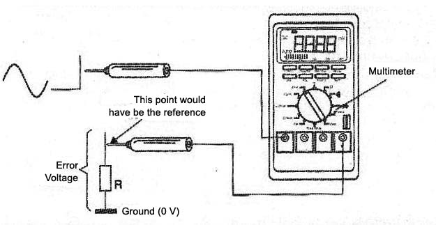
What happens is that many multimeters can present at its negative terminal a capacitance which charges the circuit changing thus the measures. Thus, we will read different voltages when the meter has its probes inverted.
The error associated with the common mode will be greater the greater is the voltage measured and the higher is its frequency. The professional must be aware of the fact, measuring in both directions when there is a suspicious result.
True RMS
As we’ve already explained the "true rms" is related to the heating voltage potential, i.e., with the power actually represented by a signal having a particular waveform as shown in Figure 2.
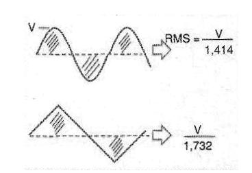
Note that this measure is different from the average value which is given by some types of multimeters that do not take into account the peaks.
The power is proportional to the square of the measurement RMS value, regardless of the waveform. In Figure 3 we have the average measurements and what happens to the calibration error to a multimeter that works only with sinusoidal signals.
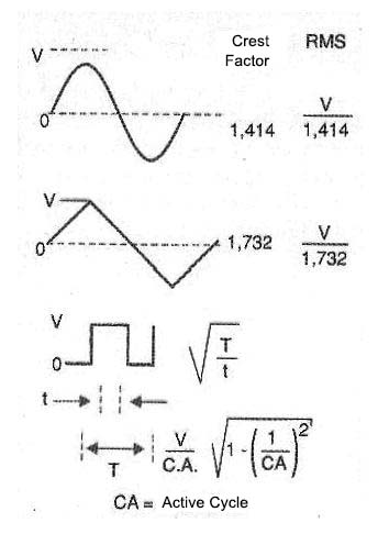
Note that for sinusoidal, triangular and square signals, AC and AC + DC value are the same since there is no DC offset, but for non-symmetrical waves like pulse trains, these voltages are rejected by a multimeter true RMS.
Crest Factor Errors
There is a misconception that "since an AC multimeter is a true RMS, its accuracy for sinusoidal waveforms applies to any waveform." Actually, the waveform of the measured signal can dramatically affect the accuracy of a measurement.
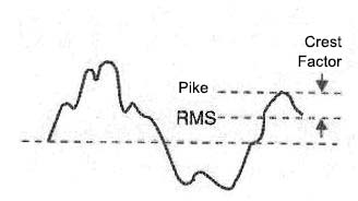
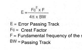
We can define the "crest factor" as a relation between the peak value and the RMS value of a waveform as shown in Figure 4.
For a pulse train, for example, the crest factor is approximately equal to the square root of the inverse of the active cycle. In general, the higher is the crest factor, the higher will be the energy contained in the higher frequency harmonics.
All multimeters have errors that depend on the crest factor. For a multimeter, the equation of Figure 5 allows to calculate the total error, taking into account the crest factor error.
Error by AC Charge
The multimeters represent a charge resistor in parallel with a capacitance which is connected to the circuit being measured, as shown in Figure 6.
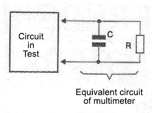
The presence of capacitance causes the impedance presented by the meter to depend on the signal frequency being measured. The higher the frequency the lower the impedance and therefore the greater will be the load that the multimeter will represent. This means that the higher the frequency of the measured signal, the greater the error introduced by the charge represented by the instrument.
Special care should be taken when measuring higher frequency voltages. The use of test leads of low capacitance is crucial in this case.
Errors in the Signal Measure of Small Intensity
When very low voltages below 100 mV are measured, one should beware of the errors which occur due to induction noise.
An exposed probe cord functions as an antenna which can capture intense noises generated by close sources which overlaps the voltage, as shown in Figure 7.
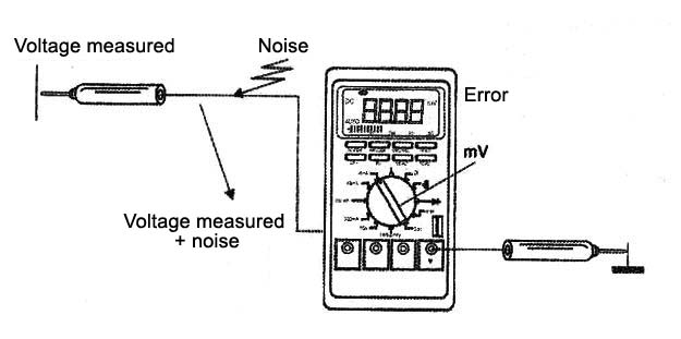
We should be careful with these spurious signals for the measurement of low voltages, if possible using shielded cables to the probes.
An important point is the signal that can be introduced into the measurement circuit by the power supply. An important caution when performing measurements with a multimeter powered by the power grid is that it is connected to the same outlet where the appliance is being analyzed. This helps minimize any feedback links to the ground, capable of generating noises affecting the measurements.
An interesting feature that can be useful in these measures is the connection of a capacitor in parallel with the multimeter input to reduce its impedance in relation to the noise. The correct value of the capacitor used must be obtained experimentally.
Errors due to the Temperature
The features of a multimeter vary with the temperature.
Even keeping the equipment in a single setting, with its functioning the temperature of the components rises causing changes in its performance.
Offset currents can appear at critical points of the circuit, affecting the measures.
Of course the variations that occur are very low, as specified for most multimeters, but they must be taken into account in certain operating conditions of the device.
Conclusion
It is not enough to have the best multimeter for your work. The introduction of errors in measurement also depends on the operator and the conditions under which the measurement is performed.
The professional who uses a digital multimeter should be aware of this fact and find out to what extent the way he is using the multimeter is not taking him to misleading results. Be aware and take into account that if the product is good, the operator is not foolproof and there can be important external factors influencing the measure.
Note: This article was originally published in 2009 code, but with the change of Agilent to Keysight, we did an update in 2015.


