The instrument described can have its calibrated scale for the devices whose consumption is known, for example, incandescent lamps and heating elements.
Once the calibration is done we can use it to have an idea of ??the consumption of some common devices.
The circuit is designed for a maximum power of 100 W, given by the diodes, but it may be slightly higher, up to about 300 W if we use diodes 1N5404 on the network of 117 V and 1N5407 on the network of 220 V.
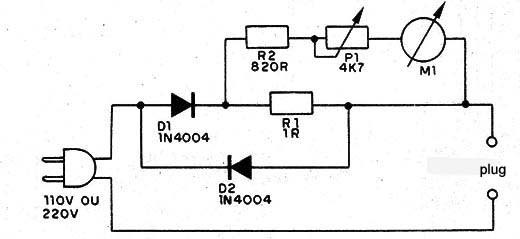
To measure consumption the circuit uses the small voltage drop on a very low value resistor, to not affect the operation of the electronics being powered.
This voltage is applied to the indicated device, which is proportional to the consumption.
Assembly
In Figure 1 we have the complete diagram of the consumption meter.

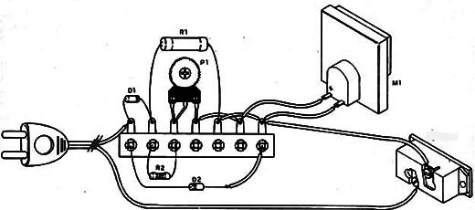
The assembly is very simple, which means that gradually the components used can be welded directly to the terminal bridge as shown in Figure 2.

On the assembly it is very important to note the position of the diodes.
The resistor R1 is wired with 5 W of dissipation and R2 of 1/8 W with any tolerance.
Use the 1N4004 or 1N4007 if the network is 117 V and 1N4007 if the network is 220 V, for the diodes.
The trimpot allows you to calibrate the instrument scale.
D1, D2 - 1N4004 (117 V) or 1N4007 (220 V) - silicon diode
M1 - microammeter from 50 to 200 µA or microamp of 0-1 mA
R1 - 1 ohm - wire resistor
R2 - 820 Ω - resistor - gray, red, brown
P1 - 4k7 Ω - trimpot
Miscellaneous:
A power cord, a plug, a terminal bridge, a box for the assembly, etc.


