
For those who do not yet have a multimeter, and who are not satisfied with a simple continuity tester, this is the intermediate instrument that will be of great use to you in your workbench. See in this article, how simple is its assembly and use.
Not all components have only two states: full driving and no driving. In fact, in electronic works we are faced with all degrees of conduction, which prevents that a simple test of continuity is a definite way of evaluating the state of components.
Ideally we would always have an instrument capable of measuring the degree of conduction and not simply indicate it, but this is the multimeter, which not everyone can have because of its high cost(*).
(*) At least in the year this article was written.
Certainly readers dream of a lower-cost intermediate instrument that can give indications of conduction degrees with good accuracy. (Figure 1)
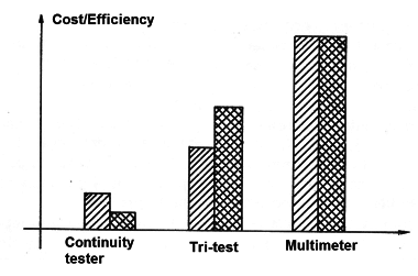
Well, this device exists and it's here. It is a status tester that provides three levels of driving directions and, in addition, the indication of no current passing (open circuit).
Using only three LEDs and a few more components, this is the instrument of the beginner, STEMer, student and hobbyist.
How it works
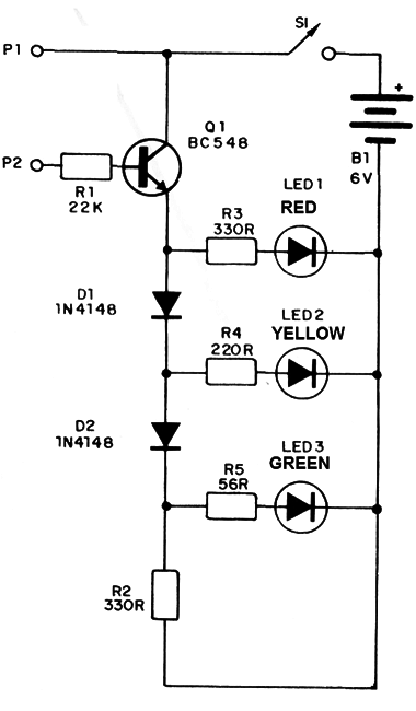
A level indicator with 3 LEDs is used which lights with a scale of the order of 0.6 V. This scaling is given by diodes D1 and D2.
A transistor in the input drives these LEDs so that we have a stepped ignition according to the conduction, that is, the resistance presented between the collector and the base. (Figure 2)
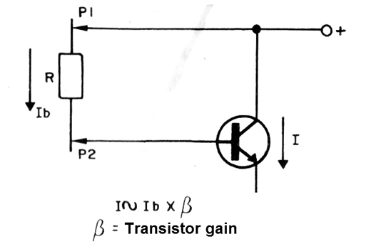
We have the following ignition according to the resistance:
Resistances greater than 700 k ohm all LEDs remain off.
Resistances between 700 and 400 k ohm, only the red LED lights up.
Resistances between 400 k and 45 k ohm, the red LED and the yellow LED light up.
Resistors between 0 and 47 k all LEDs light up.
The reader must have realized that, by turning on the LEDs, we can have an indication of the range of resistances between the probes.
Assembly
The complete circuit of the test is shown in Figure 3.
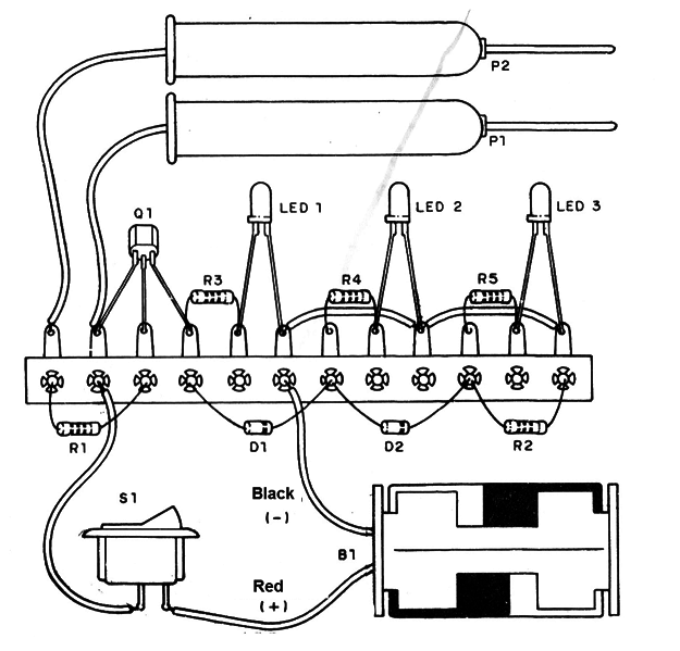
The bridge version of terminals for beginners is given in Figure 4.
We also give a printed circuit board version, which we will teach the reader to make, and which is shown in Figure 5.
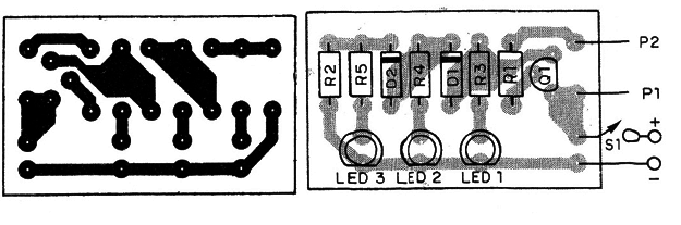
In the placement of the components observe the position of the transistor, the polarity of the diodes and LEDs. The battery also has polarity which is observed depending on the colors of the battery holder.
Making the Printed Circuit Board
It is very simple to carry out the assembly of printed circuit boards at home. You just need to have the following material:
One pen for printed circuit boards (rechargeable or not)
A board cutter
A drill
Half or one liter of iron perchloride (corrosive)
A virgin printed circuit board.
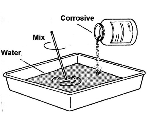
Begin by dissolving the perchloride in the water, in the proportion of 1 to 1 if it comes in the form of powder, because in some cases we can already buy the solution ready.
The solution should be prepared by slowly pouring the perchloride into the water to be agitated with a piece of wood (do not use metal). The solution can be prepared in a plastic or glass tub.
To make the board, cut a piece of the blank circuit in the measurements that the original drawing requires.
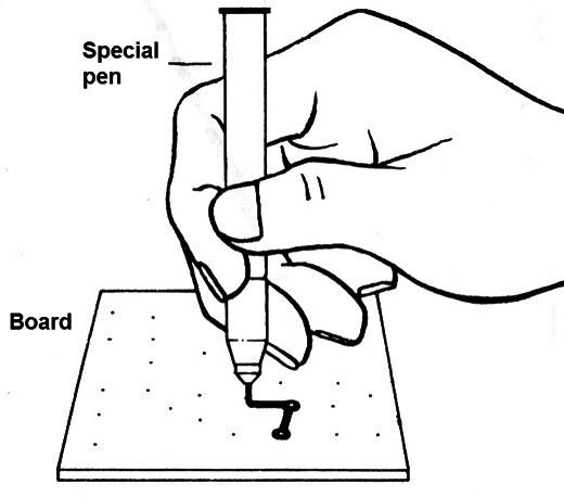
Copy the drawing onto the board using the special pen (which is not attacked by the solution). See that you will draw the black lines of the drawing, those that will not be attacked by perchloride and that will become copper strips on the board. (Figure 6)
Finished the drawing work, take the board to the tub of perchloride; Leave it in the tub for 30 minutes to 40 minutes. Time will depend on the "strength" of the corrosive solution. As you can use it many times over time it will weaken, requiring increasing time for corrosion (Figure 7).
Remove the board after this time (be careful not to stain your clothes and avoid touching the solution with your fingers. If you accidentally wet your fingers in the solution wash under running water), it must be completely corroded in the uncovered regions.
Just wash the board and remove the ink that covers the printed areas. To remove the paint you used on the drawing, use a Bombril or a cotton swab dipped in acetone or benzene.
After that, just drill the board where the terminals of the components should pass and use it.
Operation test
To test the device, simply insert new batteries into the holder and connect S1. With the tips separated, all LEDs should be off.
By connecting a 470 k resistor between the probes only the red LED lights up. By connecting a 150k resistor between the probes, the red and yellow LEDs light up, and by connecting a 10k resistor between the probes all LEDs should light up.
If any LED does not light up, see if it has not been turned upside down.
Using the Tester
To test components, simply place the probes on the terminals and take into account the resistance to be found.
Resistors: LED turns on according to the value
Diodes: In one direction the resistance is very high (no LEDs lit) in the other direction, the resistance is too low (all LEDs lit).
Coils: The winding resistance is usually less than 47 k which means that all LEDs should light when the probes are placed on their terminals.
Capacitors: very high resistance, no LED should light. If a LED (red) lights up, it signals that the capacitor is leaking and if all are lit the capacitor is shorted.
Low impedance speakers and earphones: All LEDs should light up.
Lamps: all LEDs should light, as the resistance is less than 47 k.
Trimpots and potentiometers: connecting the probes to the ends of the component, the LEDs that light up correspond to the nominal resistance (marked on the component body).
Fuses: All LEDs lit for good fuse and no LED for an open fuse.
Relays: The coil test should turn on all LEDs. NC contacts should light all LEDs and NO should light no LEDs.
Q1 - BC548 or NPN transistor equivalent
D1, D2-1N4148 or equivalent - silicon diodes for general use
LED1 - Common red LED
LED2 - Common yellow LED
LED3 - Common green LED
P1, P2 - Probes
R1 - 22k x 1/8 W - resistor (red, red, orange)
R2, R3 - 330 Ω x 1/8 W - resistor (orange, orange, brown)
R4 - 220 Ω x 1/8 W - resistor (red, red, brown)
R5 - 56 Ω x 1/8 W - resistor (green, blue, black)
S1 - single switch
B1 - 6 V - 4 small alkaline batteries
Miscellaneous:
A printed circuit board or terminal bridge, support for 4 batteries, wires, etc.


