
The tester we describe is ultra simple and provides two kinds of indications: in addition to telling whether a transistor is good or not to be used in a project, it allows us to evaluate its gain, that is, its capacity for amplification in two bands.
And, as an important additional feature, this unit will also test silicon and germanium diodes (rectifiers, general use, etc.).
Built in a box, as Figure 1 suggests, this appliance will undoubtedly be a great help on your workbench.
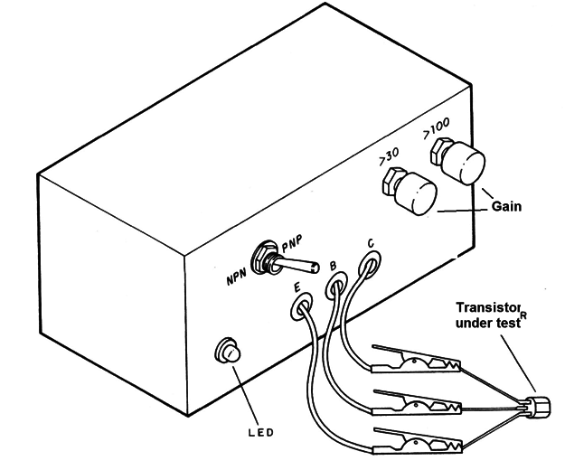
Operation requires the use of only two small, ordinary batteries that will last forever.
HOW IT WORKS
A transistor is a DC amplifier. A weak DC current, applied to the base of a transistor, should result in a stronger current between its collector and the emitter, as shown in Figure 2.
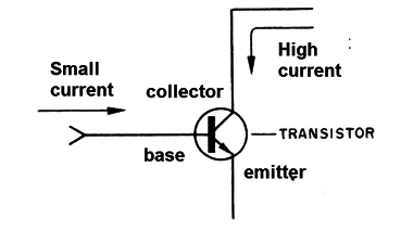
If the collector current is 100 times greater than the base current, we say that the gain of the transistor is 100 or even that it has an hFE = 100.
Common transistors, used in assemblies, can have gains ranging from 10 up to over 1,000!
To know if a transistor is good, then simply apply a weak known current at its base and check if the collector current matches the expected one.
Then we connect to the transistor collector an LED, with a resistor in series, that fixes the current that it must conduct.
Due to this LED and the resistor, we can then place a resistor of the value in the base of the transistor that, for an expected gain, results in the current that lights it.
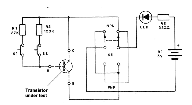
Thus, with a 100 k resistor, for the LED to light, the transistor must have a gain of at least 100 times, and for a resistor of 27 k, a gain of at least 30 times.
But, the circuit still requires some other features:
The first is the reversal of battery polarity: there are two types of transistors, the NPNs and the PNPs, which conduct the current in different ways, as shown in Figure 3.
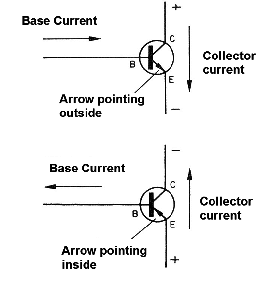
The reversal to test transistors of the two types is done by an H. switch.
Finally, we have to think of a type of defect that is common in the transistors and that can give a false indication of good state. This problem occurs with short transistors.
If you connect an LED to the transmitter's shorted transmitter, it will turn on even if there is no base current! It simply "ignores" the base current!
For this reason, we used two pressure switches (S1 and S2) to connect the base terminal during the test. Thus, if before pressing these buttons the LED is already lit with the transistor in test, it is a sign that it is shorted.
ASSEMBLY
The assembly is very simple, since few components are used, as we can see by the scheme in Figure 4.
The practical implementation of the apparatus on a terminal bridge is shown in Figure 5.
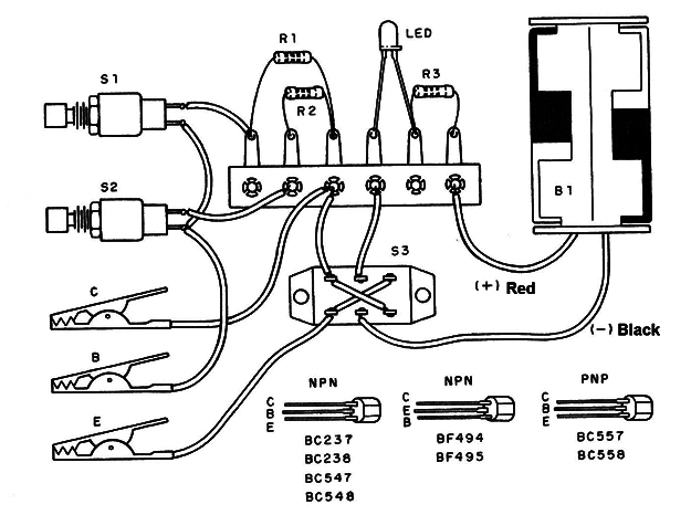
The main care you should take with the assembly is as follows:
A) The LED is common, red, and its connection must be made with the flat side or the shorter terminal connected to the switch.
B) Observe the polarity of the battery holder.
C) The switch S3 is of type 2 x 2 (reversible) or H as it is also known. Be careful with their connections.
D) The resistors are 1/8 W with the indicated values.
E) Switches S1 and S2 are usually the open pressure type, such as those used in bells.
F) To connect the transistors being tested, use alligator clips. It is convenient that they are of different colors so that their functions are differentiated:
Red: emitter
Green or blue: base
Black: collector.
Finishing the assembly, the test is simple and immediate.
TEST AND USE
Insert the batteries into the holder and connect any transistor to the alligator claws, following its terminal arrangement. The key S3 must be in the position corresponding to the type: NPN or PNP.
If the LED already lights up with the transistor connection it is because it is shorted.
If not, press S2 first. If the LED lights up, the transistor is fine and has gain above 100. If it does not light up, press S1. Turning on now, the transistor is good and has gain above 30.
If it does not light up, the transistor is bad, or else it must have a gain below 30 (the BC, BD, and BF series transistors typically all have a gain greater than 30).
To test a diode, connect it between the taser's claws C and E.
If the LED lights up, move S3 to the other position. The LED should go off.
If the LED does not light up, move S3 to the other position. The LED should light up.
If the LED stays on or off in both S3 positions, then the diode is shorted. There is no need to set the main switch or remove the batteries when the unit is out of use. Just keep the claws apart so it will be off.
LED - red LED, common
B1 - 3 V - 2 small alkaline batteries
R1 - 27k x 1/8 W - resistor (red, violet, orange)
R2 - 100k x 1/8 W- resistor (brown, black, yellow)
R3 - 220 Ω x 1/8 W - resistor (red, red, brown)
S1, S2 - pressure switches
S3- reversible switch 2-pole x 2 positions
Miscellaneous:
A terminal bridge, an assembly box, alligator clips, wires, welding, support for 2 small batteries, etc.
2016


