
The VU-Meter or Volume Units Meter is an instrument that measures the strength of an audio signal. In the output of a stereo audio amplifier we use two of these meters to be able to have a better control over the intensity of the signal of each channel, as shown in figure 1.
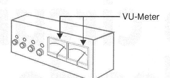
In the older equipment of the professional type it is common to use for this purpose analog meters such as those shown in figure 1, for both readability and accuracy.
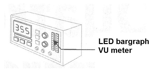
However, based on the idea that the hands of these instruments swinging to the rhythm of the music have a decorative effect too, some manufacturers went further and creating the digital version of LEDs of this instrument, turned it more into an aesthetic resource of their equipment than with the purpose of adjusting its operation, balancing the channels.
It is common, therefore, to find in the modern equipment the VUs of the Bargraph type, as shown in figure 2.
However, readers who have musical sets with powerful amplifiers (no VUs) or even tape editing studios without these features can easily add an analog VU-meter using the circuit shown.
Admitting feeds in the range of 6 to 15 V it employs only one integrated circuit and has in the input a setting that marries its characteristics to almost any audio equipment.
HOW IT WORKS
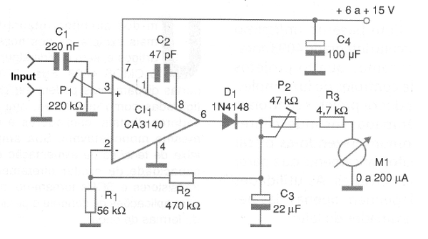
The field effect transistor operational amplifier at input CA3140 has its gain determined by the ratio of values between R1 and R1. The input impedance of the circuit is given by R1.
Thus, by applying the audio signal at the input of this circuit it has a voltage amplification and after that it is applied to diode D1 which does its rectification so as to maintain only the positive half-cycles.
The peak positive voltage of the signal carries C3 and serves to drive P2 and R3 the indicating instrument.
With the use of an adjustment like P2 we can use indicator instruments in a wide range of values. Thus, microammeter type panel indicators with 100 uA to 500 uA scalability can be used without problems in this project. The adjustment is only to prevent the pointer from hitting the end of the scale with very strong signals.
ASSEMBLY
In figure 3 we have the complete diagram of the indicator.
For a stereo version double indicators can be used and two circuits must be mounted as shown.
The arrangement of the components on a printed circuit board is shown in figure 4.
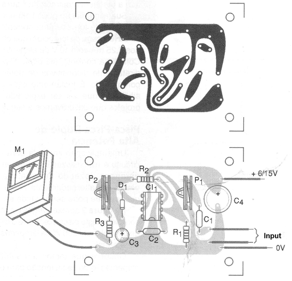
The used components are not critical and their minimum specifications of voltage, tolerance and dissipation are given in relation to materials.
The instrument can be any micro-meter of the VU-meter type even taken advantage of some equipment of sound (amplifier, for example) out of use.
The diode accepts equivalents and the power must be removed from some point in the sound circuit with which it will operate that has the voltage in the indicated range.
TEST AND USE
The circuit can be connected to the output of the speakers, signal output or even the volume control of an amplifier or other sound equipment.
P1 is set to the desired sensitivity and P2 so that the instrument needle does not strike strongly at the end of scale when all the equipment volume is opened.
The capacitor C3 acts on the frequency response of the circuit and can be increased if the reader wants a greater response to the bass sounds.
The R2 resistor can also be changed in the range of 220 k ohms to 2.2 M ohms to modify the gain of the amplifier. For very weak signals this resistor should have its value increased.
Semiconductors:
CI-1 - CA3140 - integrated circuit, operational amplifier
D1 - 1N4148 or equivalent - general purpose silicon diode
Resistors: (1/8 W, 5%)
R1 - 56k ohms
R2 - 470 k ohms
R3 - 4.7 k ohms
P1 - 220 k ohms - trimpot
P2 - 47 k ohms - trimpot
Capacitors:
C1 - 220 nF - ceramic or polyester
C2-47 pF - ceramic
C3 - 22 uF / 12 V - electrolytic
C4 - 100 uF / 16 V - electrolytic
Several:
M1 - 0-200 uA - micro-meter type VU-meter - see text
Printed circuit board, panel or enclosure for mounting, wires, solder, etc.


