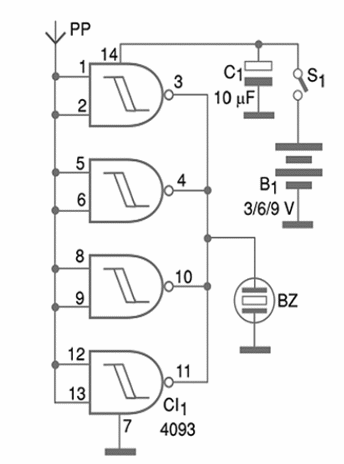
The circuit uses a very high sensitivity IC CMOS. This IC generates a tone in a transducer when a field is detected. The high sensitivity is due the extremely high impedance input of the integrated circuit. This circuit is very simple since we have only three components besides the IC. Figure 1 shows the complete schematic diagram for the detector.

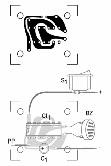
The components are placed on a printed circuit board as figure 3 shows.

The power supply, formed by common cells or a 9 V battery, and circuit can be housed into a small plastic box. The sensor is a small metal plate outside the box. The piezoelectric transducer is a common type without the internal oscillator.
A piezoelectric tweeter, without the internal transformer, can also be used as a transducer. It is also possible to use a probe as sensor. The probe will act as an antenna, picking up the irradiated hum of a power line.
Using the detector is very easy. You just have to pass it across a wall or ground where there is a power cable inside. If the buzzer produces a sound, the cable is found. The capacitor C1 must have a working voltage DC of 6 V or more. S1 is optional.
Semiconductor:
CI-1—4093—CMOS Integrated Circuit
Capacitor:
10 ?F x 6 V—electrolytic capacitor
Other:
PP1—sensor—see previous text
BZ—piezoelectric sensor—see previous text
S1—On/Off switch
B1—3 V, 6 V or 9 V—common cells or battery with holder or connector
Printed circuit board, plastic box, wires, solder, etc.


