

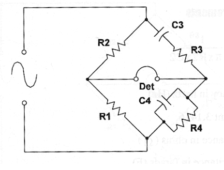
The Wien Bridge is used to capacitance and inductance measurements. Figure bellow shows the basic configuration used to this bridge. The balance indicator is chosen according the frequency of the used signal. This frequency, by it is time, is chosen according the magnitude of the capacitance or inductance to be measured.
Formula:
When balanced:
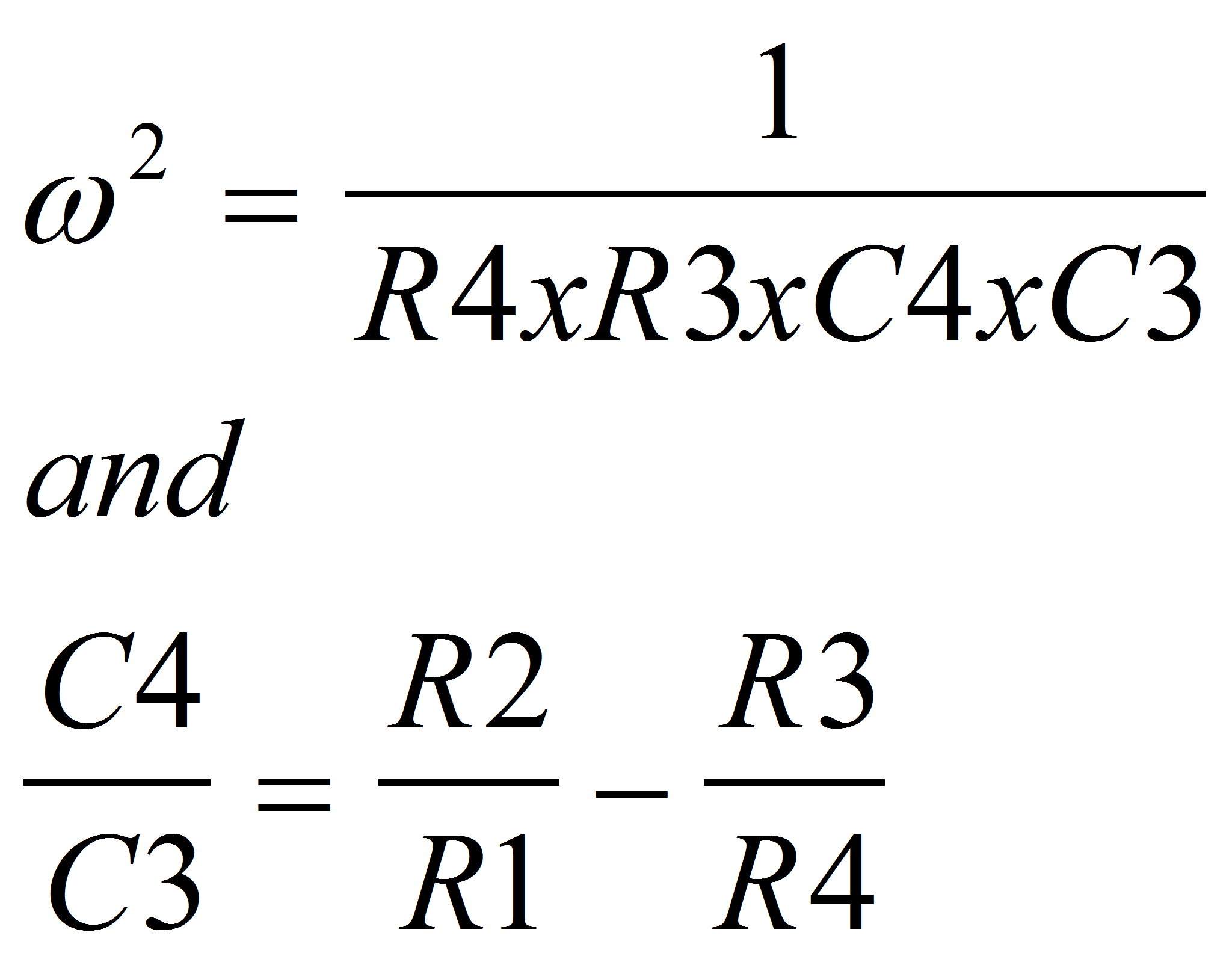
Where:
ω is 2 x π x f (f is the generator frequency in hertz - Hz)
R1, R2, R3 and R4 are the resistance in ohm (ohms)
C1, C2, C3 and C4 are the capacitances in farads (F)
Note: The bridge can be used to frequency measurements. In this cases select the capacitors and resistor as follows:
R3 = 2 x R4 and C1 = C2
The formula 2 be used to determine the frequency of a signal source:
Formula 2:
To frequency measurements:
f = 1 / (2 x ? x R2 x C2)
Where:
f is the frequency in hertz (Hz)
Π is the constant 3.14
R2 is the resistance in ohm (Ω)
C2 is the capacitance in farads (F)
Formula 3:
When balanced is also valid:
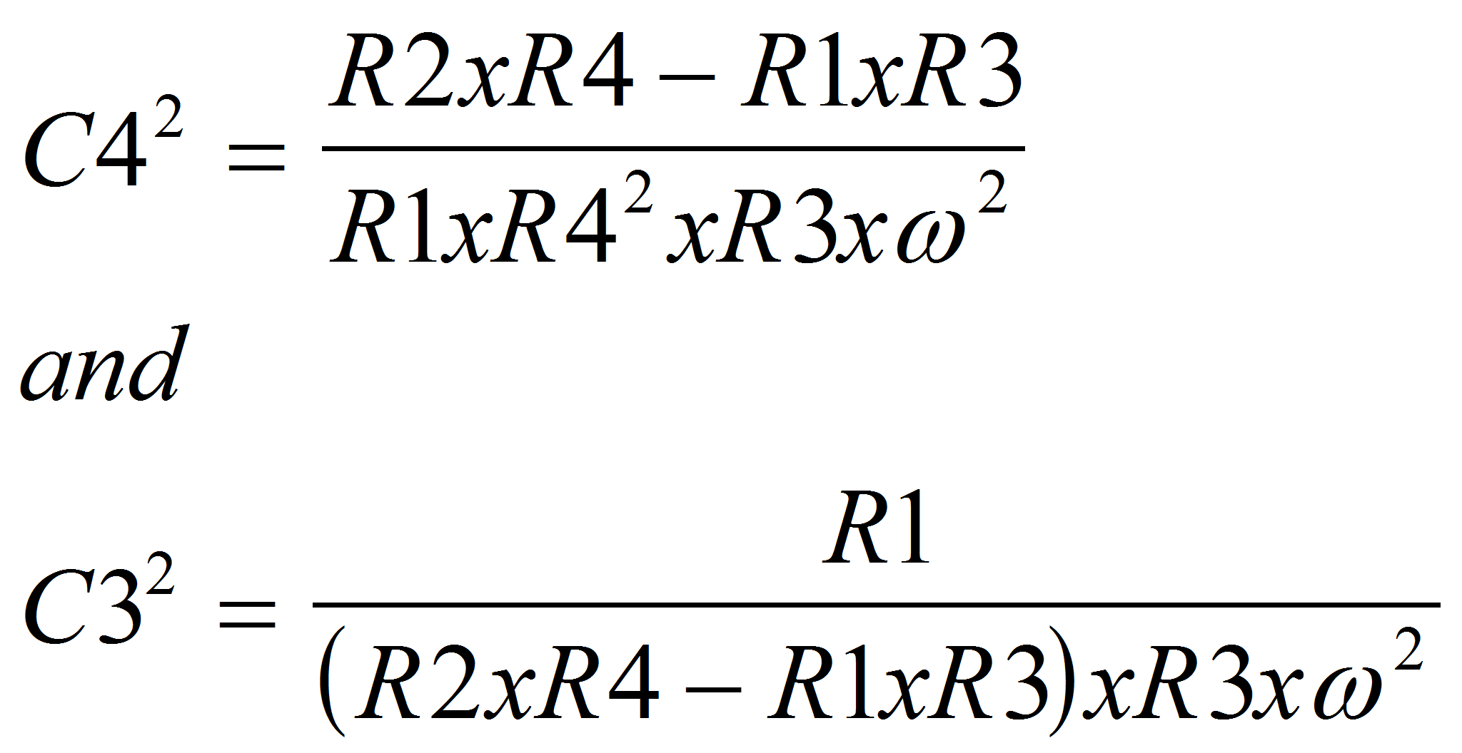
Where:
ω is 2 x π x f (f is the frequency in hertz - Hz)
R1, R2, R3 and R4 are the resistances in ohm (ohms)
C1, C2, C3 and C4 are the capacitances in farads (F)


