

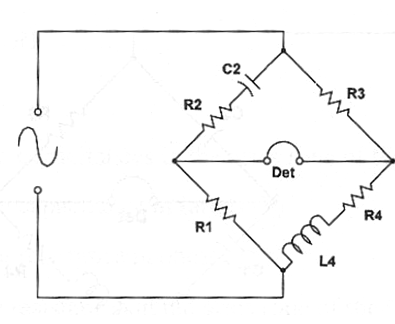
This bridge is used to inductance measurements and the results are dependent from the signal generator frequency. So, the frequency must be chosen according the magnitude of the inductance to be measured. The basic circuit is shown in figure bellow.
Formula:
When balanced:
Where:
ω = 2 x π x f (f is the frequency in hertz - Hz)
L is the unknown inductance in henry (H)
R1, R2 and R3 are resisitances in ohm (Ω) - two of them variable to balance the bridge.
R4 is the resistance associated to the coil in ohm (Ω)
C1 and C2 are capacitances in farads (F)


