

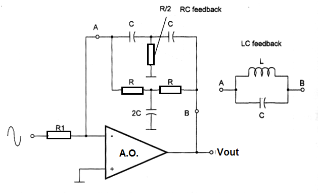
The bandpass filter shown in figure 1 can use in the feedback loop an LC ressonant circuit or a RC network. The characteristics (bandwidth, Q-factor and other ) are determined by the type of filter. The next formulas are used to calculations involving the output frequency.
Formula 1
LC feedback:
f = 1 / 2 x π x √(L x C)
Where:
f is the frequency in hertz (Hz)
L is the inductance in henry (H)
C is the capacitance in farads (F)
π is 3.1416
Formula 2
RC feedback network
f = √3 / (2 x π x R x C)
Where:
f is the frequency in hertz (Hz)
R is the resistance in ohm (Ω)
C is the capacitance in farads (F)
π is 3.1416
√3 =1.7320
Application example:
Determine R to a bandpass filter using the configuration shown in figure 1 tuned to 10 kHz where the used capacitors are 0.005 F units (5 nF).
Data:
f = 10 kHz
C = 0.005 x 10⁻⁶
R = ?
Using formula 148.2:
10 x 103 = 1.73 / (2 x 3.14 x R x 0.005 x 10⁻⁶
R = 1.73 / (6.28 x 0.005 x 10-6 x 10 x 103)
R = 1.73 / 0.628 x 10⁻³
R = 2.754 x 10³
R = 2.754 kΩ


