

The basic configuration shown in figure 1 is a parallel regulator or shunt regulator. The transistor is wired in parallel with the load shunting the current in an way the voltage in load remains constant.
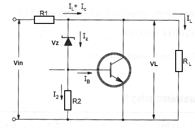
The elements to be calculated are the zener charateristics, R1 and R2 and also the transistor characteristics. The next formulas are used when some parameter are fixed.
The fixed parameters are:
UL = load voltage in volts (V)
IL (max) = maximum current in the load in amperes (A)
Ic(min) = minimum current flowing by the collector of Q in amperes (A)
Iz(min) = minimum current flowing through the zener diode in amperes (A)
Vin = input voltage in volts (V)
Vin(max) = maximum input voltage (normally 10% over Uin)
Vin(min) = minimum input voltage (normally 10% under Uin)
VBE = voltage between base end emitter - 0.6 V for silicon transistors
B(min) = minimum gain of the used transistor
Formula 1
Determining Vz:
Vz = VL – 0.6
Where:
Vz is the zener voltage in volts (V)
VL is the voltage accross the load in volts (V)
0.6 is a constant when using silicon transistor
Formula 2
IR2 (current through R2)
IR2 = Iz(min) - [ Ic(min) / B(min) ]
Where:
IR2 is the current through R2 in amperes (A)
Iz(min) is the minimum current through the zener diode in amperes (A)
Ic(min) is the minimum currente through the transistor in amperes (A)
Bmin is the minimum gain of the used transistor
Formula 3
Determining Iz(max)
Iz(max) = { [ ( Vin(max) – Vz – 0.6 ) / ( Vin(min) – Uz – 0.6 ) ] x (Iz(max) + Ic(min) + Iz(max) + Bmin x IR2) } x (1 / Bmin + 1)
Where: Iz(max) is the maximum current flowing through the zener (A)
Uin(max) is the maximum input voltage (V)
Vin(min) is the minimum input voltage (V)
Vz is the zener voltage in volts (V)
Iz(min) is the minimum zener currentin amperes (A)
Iz(max) is the maximum zener current in amperes (A)
Ic(min) is the minimum collector current in amperes (A)
Bminis the minimum transistor gain
IR2 is the current through R2 in amperes (A)
Formula 4
Calculating Ic(max):
Ic(max) = Bmin x ( Iz(max) – IR2 )
Where:
Ic(max) is the maximum current in the transistor in amperes (A)
Bmin is the minimum transistor gain
Iz(max) is the maximum zener current in amperes (A)
IR2 is the current through R2 in amperes (A)
Formula 5
Pc(max) - power dissipated by the transistor
P(max) = (Vz + 0.6) x Ic(max)
Where:
P(max) is the maximum power dissipated by the transistor in watts (W)
Vz is the zener voltage in volts (V)
Ic(max) is the maximum collector current in amperes (A)
Formula 6
Determining R2:
R2 = 0.6 / IR2
Where:
R2 is the resistance of R2 in ohm (Ω)
IR2 is the current through R2 in amperes (A)
0.6 is constant used with silicon transistors - UBE
Formula 7
PR2 - Power dissipated by R2:
PR2 = R2 x IR22
Where:
PR2 is the power dissipated by R2 in watts (W)
R2 is the resistance in ohm (Ω)
IR2 is the current through R2 in amperes (A)
Formula 8
Calculating R1:
a) R1(max)
R1(max) = ( Vin(min) – Vz – 0.6 ) / ( Iz(min) + Ic(min) + IL(max) )
b) R1(min)
R1(min) = ( Vin(max) – Vz – 0.6 ) / ( Iz(max) – Ic(max) )
c) R1
R1(min) ? R1 ? R1(max)
Where:
R1(min) is theminimum value of R1 in ohm (Ω)
R1(max) is the maximum value of R1 in ohm (Ω)
R1 is the recommended value of R1 in ohm (Ω)
Vin(min) is the minimum input voltage in volts (V)
Vin(max) is the maximum inout voltage in volts (V)
Vz is the zener voltage in volts (V)
Iz(min) is the minimum zener current in amperes (A)
Iz(max) is the maximum zener current in amperes (A)
Ic(min) is the minimum collector current in amperes (A)
Ic(max) is the maximum collector current in amperes (A)
0.6 is constant - valid for silicon transistors
Formula 9
PR1 - dissipation of R1.
PR1 = R1 x I2
Where:
PR1 is the power dissipated by R1 in watts (W)
R1 is the resistance in ohm (Ω)
I is the total current in the circuit in amperes (A)


