Three-phase circuits are more difficult to operate when we want to control them because we have signals with different phases, which are applied to a load. This fact is reflected in power control designs using SCRs or other semiconductor devices where we need to trigger these components with 120 degree phase differences to get a correct control of their operation.
How to design a power control for a load powered by a three-phase network is precisely our proposal with this simple design, whose power can be altered by the exchange of used SCRs.
OPERATION
The basic configuration for the three-phase power control is shown in figure 1.
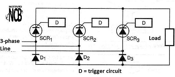
As we can see, we need to use an SCR for each phase with its independent firing circuit, which must act at the correct angle to apply the desired power to the load according to the conduction angle of that specific phase.
This means that for a power control of 0 to 100% of maximum power, each SCR must be triggered at angles ranging from 0 to 180 degrees within the feed cycle corresponding to that phase. If all three SCRs are triggered simultaneously at various driving angles, the power can be controlled, but the range will vary between 25 and 100%.
In figure 2 we present a diagram showing the driving instants with 3 SCRs fired, in the first case at different angles and in the second case at the same instant.
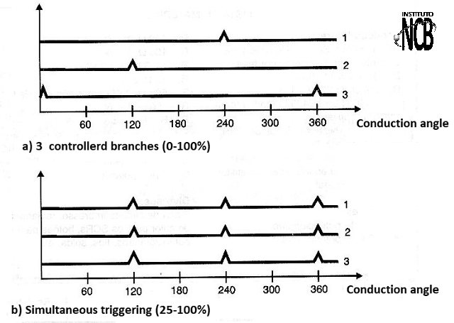
If the controlled load does not require 0 to 100% control, but can operate at maximum power reduction of up to 25% of its maximum power, a three-phase power control is considerably simplified as all three SCRs can be triggered at the same time. This is precisely our initial proposal with the circuit we present.
HOW IT WORKS
The circuit provided in figure 3 may be considered one of the simplest possibilities of having a partial power control for a load powered by three-phase mains.
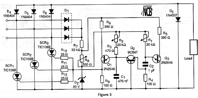
As we can see, the three SCRs are fired at the same time at angles that are determined by the firing of two uni-coupled transistors. In this circuit the diode D1 supplies the supply voltage to the control circuit. The voltage will be around 20 V, which is determined by the zener diode D2.
R2 controls the firing angle of Q1 by adjusting the load time of C1. The pulse voltage appearing at R1 when Q1 discharges through C1 is coupled simultaneously to the sluices of the three SCRs through R10, R11 and R12.
The circuit formed by Q2 and Q3 is intended to prevent Q1 from firing at any firing angle greater than 120 degrees. The good performance of this circuit depends on Q3 keeping the firing angle as close as possible to 120 degrees. This is achieved by connecting the base 2 of the unijunction transistor Q3 through R5 to a point separated from the voltage regulated by D2 through the resistor R8. This causes the Q3 timing cycle to be set accurately at just under 120 degrees.
The R8 resistor also has another purpose. By connecting base 2 of Q1 to this component, we have a voltage regulation that compensates for the variations of the mains voltage. With power in a 110 V grid this circuit maintains the voltages in the load in the 40 to 150 V range, which corresponds to a range of approximately 3.75: 1.
ASSEMBLY
SCRs should be chosen according to the power to be controlled. We suggest that the SCRs be installed in heat sinks with the connection through wires of appropriate thickness with the load to be controlled.
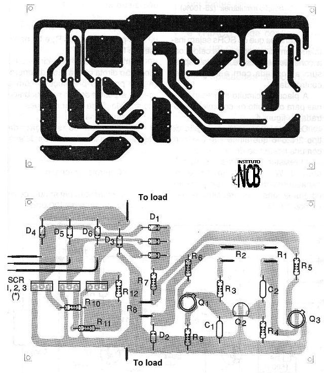
The printed circuit board only for the control circuit is shown in figure 4.
Unijunction transistors are of type 2N2646 which are still quite common in this type of application. The 33 ohm resistor must be wire with 2 W dissipation and the capacitors must be of polyester with a working voltage of at least 100 V.
Potentiometers R7 and R8 must be wire.
We remind you that this circuit has a direct connection to the power grid and that therefore precautions with exposed parts must be redoubled in order to avoid shocks.
Settings
R8 - for the compensation of voltage fluctuations of the power grid.
R2 - Voltage control
R1 - Adjust to a firing angle close to 120 degrees.
Semiconductors:
SCR1, SCR2, SCR3 - TIC106B for currents, up to 3 amps per phase.
D1 - 3 diodes 1N4004
D2 - 20 W x 1 W Zener
D3 - 1N4004 or 1N4007 - diodes (for inductive loads)
D4, D5, D6-1N5404 - silicon diodes - for loads up to 3 A
Q1, Q3-2N2646 - unijunction transistor
Q2 - BC547 or equivalent - general purpose NPN transistor
Resistors:
R1 - 10 k ohm - potentiometer
R2 - 20 k ohm - potentiometer
R3 - 470 ohm, 1/2 W
R4 - 100 ohm, 1/2 W
R5, R6 = 390 ohm, 1/2 W
R7 - 33 ohm, 2 W
R8 - 500 ohm, 2 W - wire potentiometer
R9 - 100 ohm, 1/2 W
R10, R11, R12 - 25 ohm, 1/2 W
Capacitors:
C1-470 nF-polyester
C2 - 1 ?F - polyester
Several:
Printed circuit board, heat radiators for SCRs, buttons for potentiometers, wires, solder, etc.