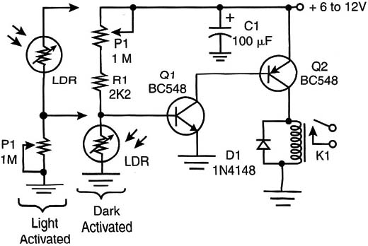
This circuit is a timed version of the circuit described in ART247E.
Very high sensitivity can be achieved with the circuit shown in Figure 1. A second transistor is added to increase the sensitivity of the circuit.

When the sensor is installed in a tube with a convergent lens, the circuit can detect light sources up to 20 meters away and even farther it in the dark (if little ambient light exists).
P1 adjusts the sensitivity, and the operating principle is the same as in the basic project (ART247E). The circuit will remain on only during the time the light is shining on the sensor.The same input stage can be adapted from the other projects (mono and bistable versions).
Parts List- High-Sensitivity Version
Q1 - BC548 general-purpose NPN silicon transistor
Q2 - BC558 general-purpose positive-negative-positive (PNP) silicon transistor
D1 - 1N4148 general-purpose silicon diode
K1 - 6-volt V x 50 mA relay
P1 - 1 MQ trimmer potentiometer
R1 - 2.2 k x 1/8-watt resistor (red, red, red)
LDR - Any round LDR or CdS cell (see text)
C1- 100 µF x 12-Volt electrolytic capacitor
PCB or terminal strip, wires, solder, etc.


