

In addition to numerous projects shields the reader can count on this site, we have publications in which they are addressed. So we can suggest our book Circuit Bench Series - 100 Shields for Arduino where the reader find 100 practical circuit designs.
For this article, we selected a good amount of simple shields that can be useful to our readers who do projects with microcontrollers.
Depending on the application and the microcontroller used, some of these shields may require minor changes to components or voltages used to power them.
1. DC Motor Driver
This circuit can be the basis for the design of small robots controlled by microcontrollers (powerless relay shield). The circuit can control motors up to 500 mA and withchanges in the transistor, higher power motors.
The described circuit can be fed by the logical steps or 2.3 or 5 V and the motor power stage with higher voltages from 5 V according the motor.
Using TIP31 and TIP32 in output stages motors can reach 2 A. These transistors must be provided with heat sinks.
In the table below have the conditions of the motors depending on the input signals.
| C1 | C2 | Motor |
| 0 | 0 | Parado |
| 0 | 1 | Sentido Normal |
| 1 | 0 | Sentido Inverso |
| 1 | 1 | Parado |
The complete schematic diagram for the shield is shown in figure 1.

Printed circuit board for the project is in figure 2.

The capacitor in parallel with the motor should eventually be increased if noted instability of operation due to the noise of the brushes
2. TTL Simple Interface
This circuit can be used as an output interface for personal computers that have a parallel port (old) and also as a shield for microcontrollers with the necessary adaptations. The components used are common.
This shield circuit or interface can be used for various purposes to control the flow of data between a microcontroller or computer, and a controlled circuit.
Power should be done with a voltage source of 5 V and outputs should take into account the available power capacity, possibly triggering power stages.
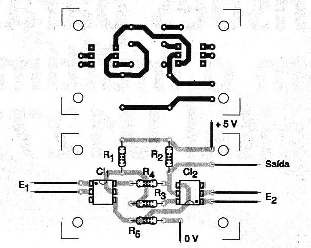
The complete diagram of the interface is given in Figure 3.

Printed circuit board for this projects is given in figure 4.

When assembling observe positions of the integrated circuits and the tracks should be carefully checked to prevent any short.
3. Optical Flip Flop
This didactic experimental project shows how you can implement optocouplers in an optical flip-flop. The circuit is compatible with TTL logic and can be used in projects that require complete isolation.
Power is sourced by a 5 V voltage and resistor must be connected in series with the LEDs. Values should be compatible with the application.
For use as a shield for microcontroller the resistor in series with the LED can be 220 Ω to 3,3 V logic 330 Ω to 5 V logic
Optocouplers equivalents may be used.
In Figure 5 we have the complete diagram of the flip-flop.

Printed circuit board for the project is shown in figure 6.
4. H-Bridge Using Power MOSFETs
The circuit shown in Figure 7 enables the control of DC motors of several amperes from CMOS logic signals.

Two of the gates of an 4011 integrated circuit are used as inverters. They are conneceted such that when one is in the high-level the output is in the low level and vice-versa..
Thus, power field effect transistors that form the H-bridge driving two by two, establishing different directions of current flow through the motor. With the high level at the input the motor rotates in one direction and the low level in the opposite direction.
The maximum controlled motor current depends only on the chosen transistors.
Power can be sourced with voltages different of 12 V, depending on the employed motor. With voltages below 9 V, the resistance between the drain and the source of the transistor begins to introduce appreciable losses for the motor.
It may be necessary to connect the motor in parallel with a capacitor of 1 to 10 µF (depolarized) to avoid instabilities caused by switching their brushes.
In Figure 8 we have a hint of the printed circuit board for this assembly.

Note that depending on the intensity of the current required by the motor, the transistors must be provided with appropriate heat radiators.
5. Shield Engine DC Bidirectional Control
The circuit shown in Figure 9 is a "half-H-bridge" and its purpose is to control the direction of rotation of a DC motor from the input signal polarity.

With a positive signal the motor rotates in the forward direction. With a negative signal in reverse. No signal or a 0 V motor voltage is stopped.
The engines of up to 2 voltages in the range from 6 to 15 V power can be controlled by this circuit.
Utilities:
• Logical Control engines in automation and mechatronics projects from sensors connected to the voltage comparators.
• Interfacing engines with computers using appropriate intermediate circuit.
• Movement direction control with automatic reversal of direct current, for example solenoids.
• Sense of movement to control in robots and other mobile devices using keys as sensors.
• PWM controls Implementation applying frequency pulses and proper polarity as direction and speed you want for the engines.
Constructive details:
The power transistors admit equivalent as the motor current or other controlled loads. These transistors must be provided with heat sinks.
The circuit requires an input current of 5 mA for at least one drive motor 500 mA with gain transistors 100.
This means a voltage of the order of at least 5 V at the input, polarity depends on the direction of rotation.
Greater gains can be achieved with power Darlington transistors.
In figure 10 we have a printed circuit board suggestion, although the configuration can be implemented on the board itself that contains the entire control circuit.

6. Relay Drive or Solenoid Shield
Arduino boards have limited current capability. Although each output can provide a good current to drive many relays or loads, the used source may suffer even heating problems.
Another problem is the fact we do not have a 5 V relay or 3.3V and wish to use a higher voltage relay. One possibility to save power microcontroller is to use Shields to separate relays that may have separate power supplies up to 12 V. This circuit shows how this is possible.
With the circuit of Figure 11 relays with 20 mA to 100 mA coil currents at voltages between 6 and 12 V, can be driven using an input current of only 5 µA.
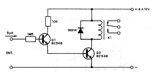
The circuit may also trigger higher loads with the replacement of Q2 for a BD135 case where the maximum current can reach 500 mA to drive solenoids and motors directly. The circuit may be powered by voltages from 6 to 12 V according to the load supplied.
Eventually the 1M5 resistor must be reduced if it is found insufficient gain of the circuit.
7. Shield - Relay Drive for Motor Control II
What distinguishes this from the prior circuit is a need for a much smaller current to drive and only one transistor.
The relay may be 5 or 12 V type as the power source and both the engine for this circuit must powered from be separate sources from the microcontroller. to avoid the motor brushes interference problem.


