

Power supplies are always of great use in the amateur service bench and hobbyists from various sectors. Providing voltages in a certain range they allow the test of small motors, lamps, relays, solenoids and other devices without the need to have the power cells or batteries, not mentioning in the economy it provides as in the repair work, adjustment or assembly time during which the batteries are requested it is more than enough to cause its complete exhaustion.
The source described has great advantages for those working with small motors, lamps and other devices that require from 0 to 12V up to 1A current. This source, however, since the type of the regulation it has, it can’t be used in electronic counters to feed sound circuits such as radios, amplifiers, etc. because it introduces noise in them (Figure 1).
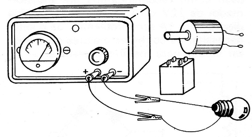
Fueled by the network of 110 or 220 V it has at its output an instrument whch indicates the output voltage, and because of the operating capacity of its components we can say that it is short-circuit proof.
Its assembly is extremely simple which means that even non-practicing electronic people who decide to build it will not find it difficult to follow strictly all the instructions that we will give.
THE CIRCUIT
As we always do, we explain the operating principle of our circuits so that the assemblers can understand what they are doing and at the same time learn a little more about electronics.
Our regulated power supply with SCR can be divided into four stages to facilitate the analysis of its operation.
In Figure 2 we have the block diagram of this source where we begin our explanations.
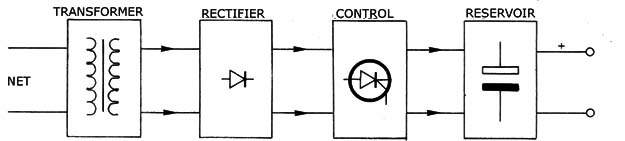
The first stage of this source is formed by a transformer which has as its function to reduce the power supply voltage that can be of 110V or 220 V for the low voltage we want to have the output, in our case 12V.
If the readers want, may use a transformer for higher voltage to the case in which its circuit voltage variation range is modified. The maximum recommended for this circuit is 28 V.
In the secondary of the transformer we obtain an alternating current though its voltage is lower.
The next step shown in Figure 3 is formed by four rectifying diodes which must be able to work with the desired current to the source.
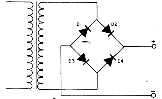
In our case as we recommend a 12V x 1A transformer, diodes can be used to 1A without a problem. If the reader needs higher currents you must use diodes for higher currents.
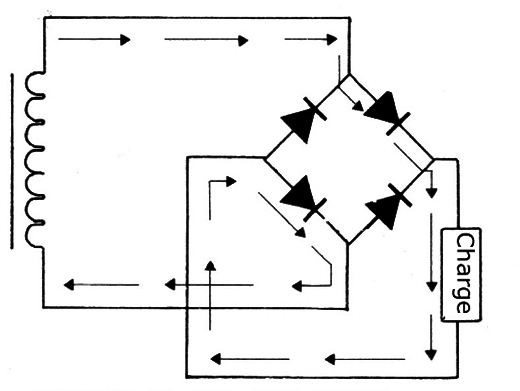
In Figure 4 is shown the operating principle of this rectifier bridge wherein each of half cycles is driven separately by two diodes in a way the current load will flow only one way.
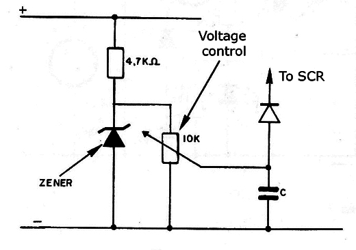
The next step is formed by a regulator which has as a basic element a SCR type C106 that can operate with currents up to 4 amperes. This is therefore the current limit that can be achieved with this regulator, since a suitable transformer and diodes are used.
The SCR works as a switch which charges a “reservoir” circuit so that its voltage is the one that is desired at the output. The trigger of this SCR is made through the voltage obtained in a splitter which has a zener diode as a reference voltage.
A pot placed in parallel with this diode allows the adjustment of the output voltage from zero to the desired maximum value, determined precisely by the type of zener used (Figure 5).
The final step is formed by the power "reservoir" which is a capacitor of great value. The source operating stability depends greatly on the value of this component. For ordinary cases where small motors, lamps, etc. are fed its value will be between 1,000 and 2,200 µF.
If the reader however wants to use the power source of audio circuits, the value must be even greater.
The capacitor acts as a reservoir accumulating energy of the pulses supplied by the SCR and providing this power continuously to the load circuit. The current will be much closer to the ideal in the load circuit, the higher the capacitor.
In the circuit output is connected a movable iron voltmeter which is the cheapest type available on the market. This instrument cannot be considered of excellent precision, but it works perfectly to get an idea of the voltage being applied to the load circuit.
Alternatively we give the connecting of a LED in the source to indicate if it is turned on. The resistor will be of 2.2k x ½ W if the source voltage is 12V. For higher voltages, proportionally greater resistors should be used.
ASSEMBLY
The choice of the box to build this power supply is subjected mainly to the transformer size.
Chosen the box, which can be metallic wooden or plastic, the tools necessary to carry out the electronics are common: a small soldering iron, a cutting pair of pliers, nose pliers and screwdrivers.
The assembly can be made directly at terminal bridges because of the reduced number of components.
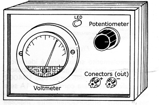
In the box panel will be exposed the strain gauge, the control of the output voltage which is the pot in which the unit can be turned on and off, the indicator LED and the connection terminals to the external circuit should have the polarity indication.
The fuse should preferably be in an accessible position to facilitate its replacement in case of need. Figure 6 gives our box suggestion for this source.
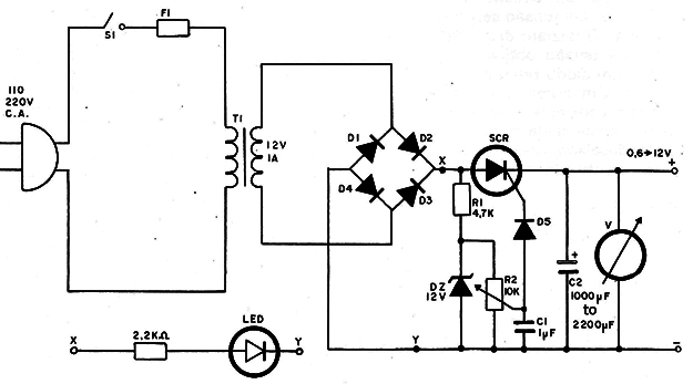
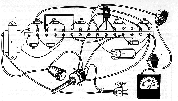
The complete diagram of the power supply is given in Figure 7.
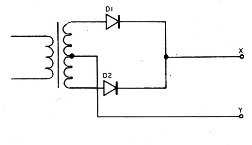
The reader must note that the transformer was used with a simple secondary hence the use of 4 diodes in rectification. If the reader has a transformer with a secondary with a central plug may make the correction with only two diodes as shown in Figure 8.
The assembly at terminal strip is shown in Figure 9, and the following are the main notes to pay attention:
a) The transformer must have a primary winding according to the mains voltage of your city, either 110 or .220V and secondary either 12V x 1A or 12 + 12V - 1A (transformer with a central plug) or another voltage up to 28V output as desired by the reader at the output. The secondary winding is identified by its thicker enameled wires.
b) The diodes may be either of type 1N4002 or equivalent to the 1A current if it is the original version. For higher currents, proportionally greater diodes should be used. There can also be used the rectifier bridges. When connecting these components you must observe carefully their position.
c) In the SCR welding besides carefully observe its polarity the reader must use a heat sink if the current being operated is greater than 1A. This means that in the original version using the heat sink is not required. Avoid excessive heat in this component.
d) The zener diode is used is for 12V if the desired maximum output voltage is of this order. For higher voltages, higher voltage diodes should be used. In any case 400 mW diodes can be used and their position should be observed carefully avoiding excess heat in their welding.
e) The diode used as D5 at the output of SCR can be of any type as, for example, a 1N4001 or its equivalents of higher voltage. Note only the polarity of this component to make its connection.
f) The potentiometer is the linear type 10k with a key. The switch is used to turn on and off the unit, also being optional its use together with the pot. In the connection of this component only observe the wire position as if there is reversing the voltage will increase when we turn it to the left and not right.
g) The filter capacitor must have an insulation voltage greater than the maximum output voltage of the source. In our case, a capacitor of 16 V can be used but if the desired tension by the reader is higher, the voltage of this component must be proportionately higher. Observe the polarity at the time of the connection.
h) The single resistor used in this assembly is 1/4 or ½ W and there is no need to observe the polarity at the time of the connection.
i) The capacitor of 1 µF may be electrolytic to 16V or as the output voltage, in which case it should be observed its polarity (the positive pole will be at the potentiometer cursor), or of metalized polyester, in which case the polarity does not need to be observed.
The recommended voltmeter is of moving iron meter 0-15V or with full-scale voltage according to what is desired.
This meterl is low cost but does not have a very high accuracy. Of course, if the reader wants to can use instead a moving coil voltmeter which can be made from a milliamp of 0-1 mA which for a 15V full scale should be associated to a resistor of approximately 15 k x ¼ W to obtain a voltmeter.
Another solution is using a LCD voltmeter modulus.
In the case of the movable iron voltmeters these do not have polarity to be connected which does not occur with the moving coil voltmeter. Be careful while handling these instruments as they are very delicate.
TEST
When the assembly is completed and checked all its connections it is very simple to test the source.
We just need to connect it to the supply network and check if the pot can sweep across the range of desired voltages. If there is excessive oscillation of the pointer at the low tensions it can be corrected by changing the value of the 1uF capacitor.
If the reader has a multimeter it will be of good use to check the voltmeter marks verifying if the indication error isn’t excessive or if there is the need to make a new scale for the same one.
SCR - C106, MCR106, IR106 or TIC106 diode controlled silicon to 50 V.
D1, D2, D3. D4 -1N4002, 1N4004 or BY127 rectifier diodes
D5 - IN4001 or the same to D1
D2 - zener diode to 12V (see text)
T1 - Transformer with the local primary and secondary network 12V x 1A (see text)
R1 - 4.7K ohm x 1 / 4W - resistor
R2 - 10k - pot with key
C1 - 1uF x 16 V - capacitor (see text)
C2 - 1 000 to 2 200, µF x 16 V - Electrolytic Capacitor
V - Movable iron voltmeter 0-15 V
F1 - 1A fuse
Miscellaneous: box, insulated terminals, terminal bridge, wires, welding, knob for the pot, etc.


