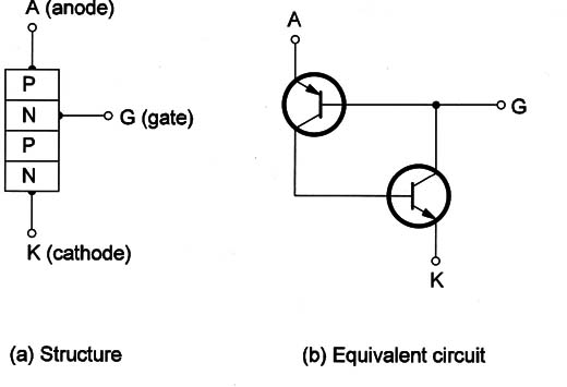
Although this device operates the same way as a UJT, its structure is different. It is a four-layer semiconductor placed in the category of components called thyristors.
The structure of a PUT is like the one shown in Figure 1.

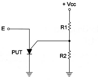
The basic difference between the UJT and the PUT is that the trigger point of a PUT can be programmed by a voltage divider placed in the anode terminal as shown in the circuit of Figure 2.
The PUT is used the same way the UJT is-as a low-frequency oscillator and timer. It is found in the same applications.

Symbol
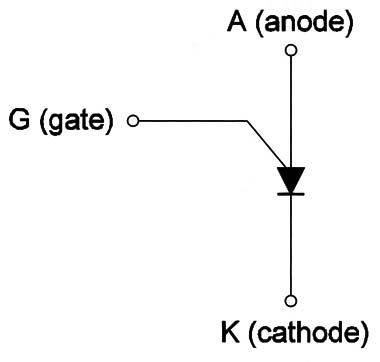
The symbol of a PUT is shown in Figure 3.

Specifications
The PUT is identified by a part number but there are electrical specifications that can be found in data sheets as the maximum voltage between anode and cathode, and the maximum operation frequency are all similar to the UJT.
Where they are found
The PUT is not a common device in modern applications, but the electrician working with electronics will find it in the same equipment where UJTs are found-timers, motor controls, audio oscillators in alarms, etc.
The use of the PUT as a discrete device is not common because manufacturers use the same function in complex integrated circuits that include other functions.
Knowing how it works is important because, although the device is not common, the function is.
Testing
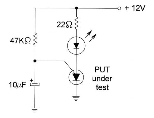
The best way to test a PUT is using a circuit where it can drive an LED (Figure 3). If the PUT is okay the LED will flash.


