

Unlike the Hall sensors which generate a voltage when subjected to a magnetic field, the magneto-resistive sensors have their resistance changed in the presence of a field.
Having a typical configuration in bridge, for reasons we’ve already covered in other articles of this same site, these sensors can be used to sense current in control systems, magnetic fields of moving magnets or metal parts in many other applications.
We proceed with some practical circuits for this type of sensors based on technical documentation of Zetex.
The sensors indicated have the ZMY prefix for the types with SOT2235 wrappers and ZMZ for those available in E-line wrappers.
The number 20 indicates that the resistance bridge is 2 kohms, although in practice the value 1.7 kohms may also be adopted.
For types that already have an internal polarization magnet, the M suffix is used.
Proximity Sensor 1
The first indicated circuit is shown in Figure 1, consisting on a proximity sensor which uses of the known LM339 voltage comparator.
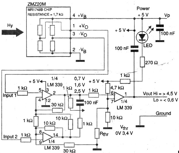
In this circuit, the output signal is used to trigger a LED, but other loads can be adapted as power load control elements.
In some cases it may be necessary to add some type of feedback in the system to provide some hysteresis. This is required to prevent oscillations in the drive threshold or shutdown.
The circuit is powered by 5 V and the sensor used is ZM220M.
Proximity Detector 2
In Figure 2 we have a second circuit suggested by Zetex, using its ZMX50MTS sensor.

This circuit uses a power FET and can drive directly a higher power load such as a relay or solenoid.
The circuit provides a rectangular signal whose setting of the trigger point (threshold) is done in two trimmers. It is powered with a voltage of 10 V.
A possible application for this type of circuit is in the rotation measurement of a work piece as illustrated in Figure 3. The sensor provides a rectangular signal to be used by an external logic circuit or a microcontroller.

The rectangular signal can be used to measure the rotational speed of the work piece or indicate its position. One possibility consists on the simultaneous use of two sensors to obtain an indication of the rotation way of the piece and its speed.
A second possibility for the use of proximity sensors would be to detect the current conductors through the magnetic field created by their movement.
Recalling that the field has an orientation that depends on the current direction we can position the sensor to operate with this field, as Figure 4 displays.

The sensor sensitivity allows the trigger of some circuit as well as the measure of the current intensity.
Current Meter
The circuit shown in Figure 5 is suitable for measuring the current of a motor.

In this case we used the current sensor ZMC05, which internally contains a conductor that generates a field sensed by the magneto-resistive bridge. The circuit intends to measure currents up to intensity of 5 A.
The chip inner conductor consists of a flat metal piece near the magneto-resistive bridge. This piece, so as to present a minimum of resistance and, therefore, losse in the motor, have a robust construction according to the current intensity that must be handled.
The insulation between the metal part and the sensor is high, thus enabling the engine circuit to operate with high voltage without the danger of it influence the sensor circuit. To measure currents up to 10 A can be used ZMC10 sensor.
See the main advantage of using this type of sensor is that it operates according to a principle similar to that of optocouplers with full galvanic isolation.
Rotational Measure with the ZMT31
The magneto-resistive sensors can be used also for measuring position, ie the angle of a magnet which rotates, through the signal produced at its output. In Figure 6, for example, we illustrate the curve of the output voltage of a sensor ZMT31 in function of the angle of a magnet placed nearby.

For this application, the magnet can be attached to a mechanical part that rotates and which we want to know its position through a sensor - see Figure 7.

The sensor may provide an output signal in function of the positioning angle of the small magnet.
Conclusion
The magneto-resistive sensors can be used as proximity sensors and also on equivalent arrangements to the optocouplers, but working with magnetic fields, as we have seen.
The current sensing in a circuit is one of those applications for which the components themselves can be obtained easily.


