
The introduction already allows the reader to have an idea of ??the fun they can get at the expense of the intermittent cricket-like noise which this device can produce.
Operating with only 2 small batteries, and reduced in size, it can be hidden anywhere, which makes it difficult to locate it.
The secret of this "electronic cricket" which only sings in the dark is a light sensitive component that only turns it on when there is absence of light and turns it off in the presence of light.
You can probably imagine the "despair" of your friends trying to sleep with the singing of this cricket and every time they turn on the lights it stops singing and can not be found (Figure 1).

Two important features should be the circuit for this game: to be small enough to be easily hidden in your friend's room (in a place where the lights can reach it) and still produce a low noise, which imitates a cricket, relatively weak to be just "annoying" and not facilitate its location in the dark.
Weak noises prevent our sense of direction from working normally which makes it difficult to locate the source.
As you will see, there are few components used in this assembly, which require neither special techniques nor deep knowledge from the assemblers. Follow our instructions and soon your cricket will be singing ... in the room of the others, of course!
HOW IT WORKS
In Figure 2 we have a simplified diagram of our electronic cricket, where, with simple words, we will try to explain its operation.

We then have two blocks representing two "oscillator" circuits. The first one producing the high sounds of the cricket and the second making its intermittence, that is, turning it on and off at regular intervals to give the beeps which characterize the device.
Let's see how the circuits work separately.
To produce the sound of a cricket, very sharp, we use a circuit called "oscillator" which uses two transistors, represented as shown in Figure 3.

This circuit is called an oscillator because it produces "electric oscillations" which applied to a speaker allows us to obtain sounds. The sound produced will depend on the frequency of the oscillator, while the frequency of the oscillator depends fundamentally on the capacitor C1 in the circuit.
This means that to make the sound lower or higher in range, we change the value of this component. In our case, by the use of a second component, we can make small adjustments in this sound, as the reader will see.
Powered by 3 V, this oscillator circuit can produce sounds at the desired level on a small speaker.
As cricket does not sing continuously, but intermittently, we have to interrupt the sound alternately by controlling the operation of the oscillator.
This is done by the circuit of the second block which is called "astable multivibrator" and which is represented by the circuit in Figure 4.

This circuit takes two more transistors as basic elements, and these transistors are connected so that at each moment only one of them conducts.
Thus, depending on the values ??of the capacitors C1 and C2 of this circuit, we can cause one transistor to drive for a certain time and the other as well.
In our case, we calculated a capacitor to give the interval between the singing of the cricket and the other to give the duration of the song. The reader can change the values of these capacitors from the original project and modify the operation of the cricket. In Figure 5 we give a graph where we represent the "signals" of this circuit and the final oscillator.

To control the multivibrator and therefore trigger the cricket, there is, in the oscillator circuit, a light sensitive element called LDR.
This LDR consists of a component, which changes resistance according to the light. When light hits its sensitive surface made of cadmium sulfide, electrons are released and it begins to conduct current.
In the dark, electrons are not released and it does not conduct current. This means that the LDR has low light resistance and high dark resistance.
In our circuit, the LDR is connected in such a way that it controls the operation of the oscillator. In the dark, it allows the cricket to function and in the light it lets the current flow in a certain way it inhibits the oscillator.
Both the multivibrator and the oscillator are supplied with a 3 V voltage from two common small batteries.
As the reader can tell, the power consumption of the "electronic cricket" is so small that it can stay connected all night long, without wearing out the batteries.
THE MATERIAL
All the material used in this assembly can be obtained easily in the houses of electronic material and, even, taken from old abandoned devices.
Our suggestion to the assembly is a box as shown in Figure 6. This box is ideally sized to accommodate the unit as long as it is made on a printed circuit board.

For a simplified assembly on a terminal bridge, recommended for beginners who do not have the printed circuit laboratory, it is necessary to use a slightly larger box.
Note that the dimensions of the box depend fundamentally on the size of the speaker used. Our recommendation is to use a 5 cm speaker of the type found in portable radios, but other larger ones may be used as long as the box is prepared to receive them.
Transistors are the components that the reader must acquire first, along with the LDR. Note that three NPN type transistors and one PNP type transistor are used.
For the PNP we give as the basic type the BC 307, but equivalents like the BC308, BC 557 and BC558 can be used.
The LDR is of the average type whose shape can be seen in the drawings. This component can be found in some types of old TVs, which use it as an automatic brightness control within its panel installation.
If the reader has one of these unused TVs, you can take advantage from it (Figure 7).

To purchase this component, just ask for a common LDR.
The speaker, as we have explained, can be practically of any type, being able to be bought or taken advantage from old radios.
Resistors and capacitors are all the common types, being easily obtained and also possible to use the ones from old appliances.
In this case, look closely at the values ??of the resistors that are determined by their colored rings and make sure that the capacitors are in good condition, especially the electrolytes.
The potentiometers do not necessarily need to have the recommended values ??in the material list, these components admitting a 100% tolerance, which means that potentiometers with half or double the indicated values ??will still work perfectly.
This wide range of allowable values ??will facilitate the use from these older device components by the readers who want to spend less money.
As additional assembly hardware the reader will still need a holder for two small batteries, knobs for the potentiometers, wires and welding.
All this material can be achieved easily, suggesting that the battery holder and knobs can be taken from old radios.
For the assembly on printed circuit boards the reader must still have the resources to make it and if you choose the bridge assembly you must purchase a bridge of the miniature type, as shown in the drawings in this article.
ASSEMBLY
Start building your cricket by preparing the box according to the dimensions of the available speaker and drilling for the LDR if the box is made of opaque material, and the control potentiometers.
Possessing the printed circuit board or terminal bridge, you can weld the smaller components but for this you should be careful.
We have in Figure 8 the complete cricket diagram.

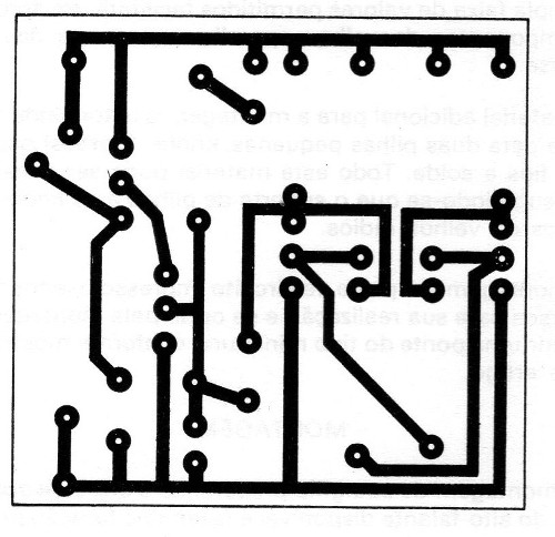
Figure 9 shows the layout of the components for the printed circuit board assembly.

For the terminal bridge assembly, Figure 10 shows the details of the connections of the components.

Start the assembly by welding the transistors observing that three of them are NPN and one PNP. Be careful not to make any changes! See the position of these components on both the terminal bridge and the printed circuit board given by the flat part of its housing.
Weld the resistors, observing their values ??that are given by the colored rings, Cut their terminals at the appropriate length to do the welding on the bridge, and on the printed circuit board, only after welding should you cut the excesses of the terminals underneath the board.
Weld the electrolytic capacitors, noting that these components have the right polarity for bonding. If there is a reversal, the device may not function.
Look carefully at the values ??of these components before placing them. If you want to try other values ??later to change the effects, leave the capacitor placement for last.
No special care is required to weld the polyester capacitor other than heat. Do the welding quickly. This component also does not have the right polarity for connection.
With all welded components on the board or terminal bridge, make your connections with the components that are attached to the housing.
To make the connection of the potentiometers, use coated wire and observe the position of the terminals where the welding is done. The wire should be neither too long nor too short.
To make the connection of the LDR, note that this component must be placed in a certain way in the box that it receives the external light. Weld quickly so that the heat from the iron does not damage the component.
To weld the wires of the battery holder the polarity must be observed.
Here we have two options: if the reader used a general switch in conjunction with the potentiometer, you should make the positive wire of the battery holder go to this component. If you used a separate switch, also note that it is the positive wire from the battery holder that goes to it.
Of course, there is the possibility of eliminating this component switching off the device by simply removing the batteries from their holder.
The loudspeaker connection is simpler and the appropriate length of wire must be used.
After the assembly is finished, check all the connections. If everything is in order, test the operation.
THE FINAL TEST
Insert the batteries into the holder and turn on the main switch (if used). With the LDR illuminated, nothing should happen.
Cover the LDR and adjust the two potentiometers until you hear the characteristic noise of a cricket. Leave the potentiometers set to this position.
Uncover the LDR so that it receives the ambient light. At this point the cricket should stop "singing".
Check how much light it takes to make it stop singing to get an idea of how to use it.
If the cricket does not oscillate, check all of its assembly, especially the part concerning the position of the transistors. If possible, check the bridge or board assembly by the diagram.
HOW TO PLAY
If you want to play with a friend of yours or with your siblings, hide the cricket in the room where it can receive the light from the ceiling lamp.
In Figure 11 we give an idea of ??how this placement should be done.

Just switch on the unit a little before your friend goes to bed when the room lights are still on. It will be convenient to do a performance test first, turning off the lights to see if the cricket actually sings.
Q1, Q2, Q3-BC237 or equivalent (BC238, BC547, BC548)
Q4 - BC307 or equivalent (BC308, BC557, BC558)
LDR - Common LDR
P1 - 220 k - potentiometer
P2 - 470 k - potentiometer
R1, R4 - 1.2 k x 1/8 W - resistor (brown, red, red)
R2, R3 - 47k x 1/8 W - resistors (yellow, violet, orange)
R5 - 10k x 1/8 W - resistor (brown, black, orange)
C1 - 47 uF at 1000 uF x 12 V - electrolytic capacitor (higher value, longer range between the cricket singing)
C2 - 22 uF or 47 uF x 12 V - electrolytic capacitor (determines the duration of the cricket song)
C3 - 22 nF or other near value - polyester capacitor
C4 - 22 uF x 12 V - electrolytic capacitor
FTE - 8-ohm speaker
B1 - 3 V battery - 2 small cells
S1 - Single switch (optional)
Miscellaneous: terminal bridge or printed circuit board, assembly box, wires, welding, knobs for the potentiometers, etc.


