
You press a switch and a counter starts to "run" generating random numbers between 0 and 9. The four LEDs that indicate these numbers flash quickly so that the player can not have any control over them. When the player releases the switch the meter does not stop immediately, but slows down gradually until a few seconds later, only a combination of LEDs is lit. This combination represents in binary the number drawn.
For a new draw, simply press the switch again and wait.
The circuit is powered with a voltage of 5 V which can come from common or source batteries and for its assembly we use a single low cost TTL integrated circuit, type 7490.
Build your device in a box and have fun with a set of values ??that we will also propose in this article.
HOW IT WORKS
To explain the principle of operation of our “raffler” we will start from the block diagram in Figure 1.
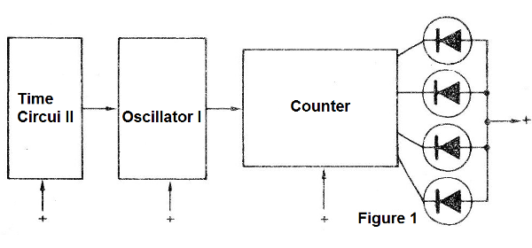
The first block represents an oscillator whose function is to produce a random number of pulses that will determine the number drawn. Note that this oscillator does not necessarily have to produce 1 to 10 pulses, but any number, since once it reaches 10, the next circuit, whose function is to count these pulses, starts again. Thus, we can improve the performance of the “raffle” by actually getting a random number if the number of pulses generated is as large as possible.
In our case, the number of pulses generated depends on the characteristics of the components used, and from the moment the player releases the trigger button it is produced from 20 to 100 pulses.
The circuit used to generate the pulses is based on a unijunction transistor. It is a relaxation oscillator which has the basic diagram in Figure 2.
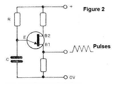
This oscillator operates as follows: the single-acting transistor is initially switched off. A very high resistance is then manifested between its emitter and the base B1. This allows the capacitor to charge slowly through the resistor in series.
The voltage on the capacitor then rises until the triggering point of the unijunction transistor is reached. When this happens, the transistor will present a very low resistance between the emitter and the base B1, so that there will be immediate and almost total discharge of the capacitor. This produces a high-intensity pulse in the resistor connected to the base B1.
With the discharge of the capacitor, the transistor returns to its initial state of non-conduction and a new cycle begins.
As long as there is power available to charge the capacitor, the oscillations are produced and consequently a number of pulses at the output of the circuit.
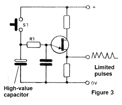
If the triggering switch were connected directly to the RC circuit, which determines the oscillations, the operation would be as follows: by pressing the switch the circuit would start and stop immediately when we release.
This behavior is not desirable since it allows the player, observing the LEDs to light, to release the switch at the moment the desired number is obtained.
To avoid this, we do and connect in parallel with the resistor and the capacitor of the oscillator a second high-value capacitor, whose function is to provide certain inertia to the circuit. When we release the switch, this capacitor discharges for some time into the oscillator producing an indeterminate number of additional pulses. This number will be between 20 and 100 depending on the value of the capacitor. (Figure 3)
The next stage of the circuit consists of a counter, which can be adjusted to operate in two ways: counting up to 2 and counting up to 5. It is a divisor by 2 and divisor by 5, which combined can result in a counter or divider up to 10 .
We are talking about the TTL 7490 integrated circuit that can be easily found in our trade.
In Figure 4, we have the aspect of this integrated, observing its 4 output terminals and the signal forms which can be obtained in these outputs.
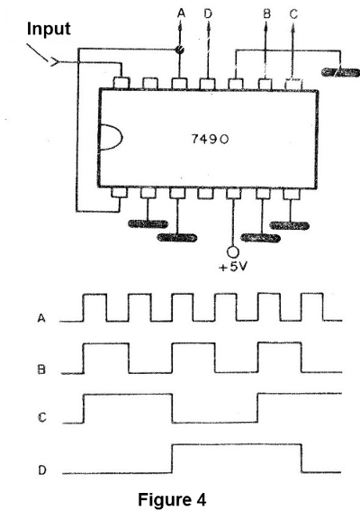
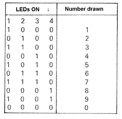
Note that, like all digital circuits, there are two signal levels at the output: signal presence (voltage around 5V) is indicated by "1" and no signal (zero voltage) by "0" or LO.
Combining then the 1 and 0 we can have the numbers drawn from 0 to 9.
In order to obtain the visualization of the levels, we connect to each of the 4 outputs LED indicators, in the case of LEDs, which can operate with the low currents that we have.
By giving a relative value or "weight" to each LED we can form combinations which give us all values ??between 0 and 9. As shown in the table, the value obtained is given by the sum of the values ??that the LEDs represent:
The LEDs must be equipped with current limiting elements, which are resistors. The resistors must not be reduced or eliminated, so that the overload of the integrated one does not occur.
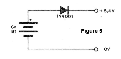
The power supply to the circuit can be done in two ways:
One of them is to associate 4 cells, obtaining 6 V.
As the TTL integrators are fed with voltages between 4.5 and 5.5 V (nominal 5 V), we make the reduction with a diode, as shown in Figure 5.
ASSEMBLY
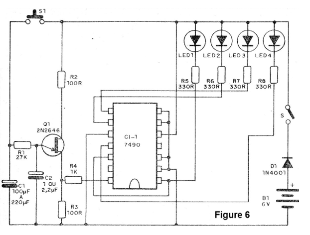
In Figure 6 we have the complete diagram of the apparatus and the printed circuit board is shown in Figure 7.
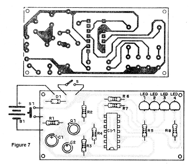
We suggest the use of DlL socket for the integrated one, in order to facilitate its replacement and to avoid the heat generated in the welding process.
In the assembly we must be careful mainly with the following:
Observe the polarity of the LEDs, the diode, and also the position of the integrated circuit and electrolytes.
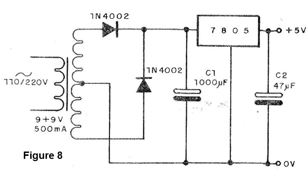
If using power supply instead of batteries, as a second option use a voltage regulator, as shown in Figure 8.
The working voltage of the electrolytes is 6 V or more, and the resistors are all 1/8 or ¼ W.
The color of the LEDs is not important, and can be differentiated if the reader wants.
An interesting possibility of play is shown in Figure 9 where we have a kind of mini arcade in which the count is given by the sum of the lightings.
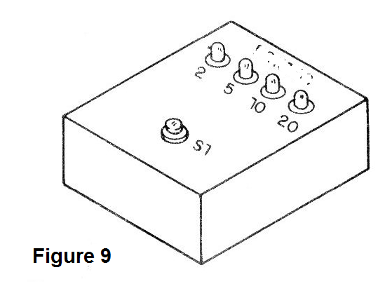
The LEDs of 2, 5 and 20 points lit up indicate 27 points for the player.
Test and use
Simply plug the batteries into the holder or turn on the power and press the switch. The LEDs must run and when the pressure switch is released they should stop after a few seconds at the value given by the combination of the LEDs.
If this does not occur, check the oscillation of the unijunction first.
To check the oscillation you can connect a small speaker in parallel with the 100 ohm resistor. There should be roulette-like noise when we press S1. If this does not happen the transistor is in trouble or connected wrong.
If the noise does occur but the LEDs do not blink, then there may be trouble shooting the integrated. Try increasing the R3 value to 220 ohms.
If no LEDs light up, check their polarity and a multimeter if the corresponding output is triggered.
To check if the integrated is counting, you can apply rectangular pulses of 5 V at the input of pin 14.
It is only necessary to use the appliance after all this.
Cl-1 - 7490 - TTL integrated circuit
Q1 - 2N2646 - unijunction transistor
LED1 to LED4 - Common red LEDs
D1 - 1N4001 or equivalent
B1 - 4 alkaline batteries - 6 V or source (see text)
S1 - pressure switch
C1 - 100 to 470, uF - electrolytic capacitor
C2-470 nF to 2.2, uF - electrolytic capacitor
R1 - 27k - resistor (red, violet, orange)
R2 - R3 - 100 ohms - resistors (brown, black, brown)
R4 - 1k - resistor (brown, black, red)
R5 to R8 - 330 ohms - resistors (orange, orange, brown)
Miscellaneous: printed circuit board, assembly box, battery holder, etc.


