
What we are describing is a wireless telegraph system in which transmission is made by the earth. With an appropriate installation, distances greater than 200 meters can be achieved, and in some cases even much more, depending also on the sensitivity of the receiver.
For simpler cases the transmitter and a simple headset are enough, but for greater distances we can use amplifier stages of several types.
The transmitting device consists of only 3 components, whereas the receiver in the basic version has only 1 component.
The operation is done with batteries and the signals consist of pulses whose intervals determine the coding.
HOW IT WORKS
When we connect a generator to distant points on the ground by means of bars, as shown in Figure 1, a "field of currents" is created.
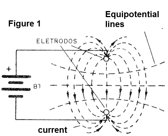
These currents obey a well-defined pattern of conductive characteristics of the soil.
In these lines, which define the field of current, can be found points of the same potential, that is, "equipotential" lines that are shown in the same figure.
If we connect a sensitive instrument at two points on the same equipotential line, the read voltage will be zero. However, if we connect the same instrument on different lines, the read voltage will be different from zero, with a current flowing. There is then a power transmission from the source to this instrument, which is the receiver.
In our telegraph, we replace the source of energy by a pulsator which sends electrical impulses, that are nothing more than currents more or less intense of short duration.
The receiver is then switched on, so as to receive the maximum voltage, then on different lines of potentials, if possible, the farthest ones.
Each pulse of the transmitter will then induce a current in the receiver which, being a phone, produces an audible click.
In Figure 2 we have the two most common ways to install the receiver: parallel or tandem boards.
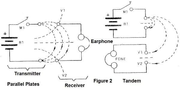
Both configurations give satisfactory effects in both transmission and reception.
We note that this transmission system is nothing new. During the second great war, being forced out of the air, radio amateurs linked oscillators, amplifiers and many other "devices" to earth, thus continuing their conversations over even relatively large distances.
ASSEMBLY
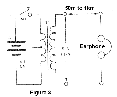
In Figure 3 we have the diagram of the transmitter and also of the receiver which are quite simple.
The actual appearance of the assembly is shown in Figure 4.
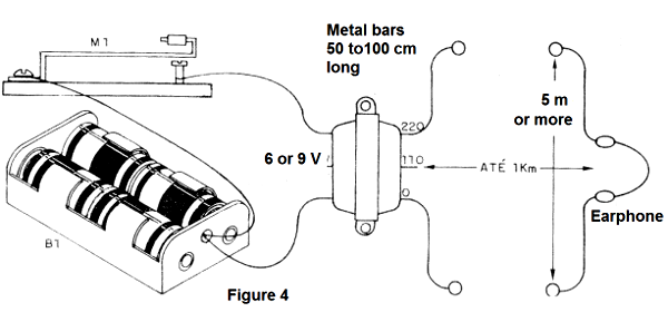
Transmitting electrodes is very important to achieve the greatest possible range.
In the first place their separation should be as great as possible. A separation of at least 5 meters is necessary to be able to exceed 50 meters of distance.
This applies to both: the receiver and the transmitter.
The soil where the electrodes are buried must also be moist and preferably not sandy. The electrodes can be either metal bars or pieces with at least 20 x 20 cm dimensions.
The transformers can either be output from old valve or power supply radios. Experiments can be done with connections in their sockets to obtain the combination, which best matches the impedance of the system with that of the ground, and thus allows greater range.
In Figure 5 we have a transistorized amplifier that can aid in the reception and even allow to hear the sounds emitted in a small speaker.
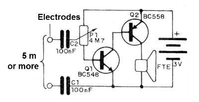
The potentiometer acts as a sensitivity control and the circuit is supplied with a voltage of only 3 V.
The maximum range will depend greatly on the type of soil, the separation of the electrodes and also the sensitivity of the receiver.
The power supply to the transmitter can be made from 4 alkaline batteries, preferably of the medium type.
Never leave the manipulator pressed for more than a fraction of a second, as the current is closed and the batteries drain quickly.
You can try transmitting with higher voltages up to the limit of 12 V.
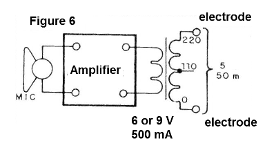
If you have an audio amplifier, try connecting like in Figure 6.
With this system, you can transmit audio tones and even your voice.
The range of the system will depend on the power of the amplifier. With 10 watts, you can easily reach 300 meters using a good receiver system.
The transformer is fundamental in this system.
Simple Receiver
B1 - 4 or 8 medium or large stacks
M1 - manipulator
T1 - 6 + 6, 9 + 9 or 12 + 12 V transformer with 500 mA at 1 A and primary of 110 V or 220 V or transformer output for radios
F1 - High impedance earphone.
Transistorized Receiver
Q1 - C548 - general purpose NPN transistor
Q2 - BC558 - general purpose PNP transistor
FTE - low impedance speaker or handset
B1 - 3 V - 2 small alkaline batteries
P1 - 4M7 - potentiometer
C1, C2 - 100 nF - ceramic capacitors
Miscellaneous: electrodes, wires, welding, etc.


