
How to measure the strength that each one has in their hands? There are, for this purpose, special dynamometers, which are used in gyms and even in medical offices, but for professional purpose.
What we propose in this article is a simple game to check who is the strongest. Bets and pranks may be made.
What we have is an electronic device which accurately measures the strength that each one has in their hands when squeezing a lever. A spring system means that more and more force is required to squeeze it to the maximum.
The indicator used is of the progressive type with 5 LEDs which light up in greater number the greater the force applied. If the force is small (only weak) only one LED lights up.
If somebody manages to turn on all the LEDs, then we'll be in front of Superman!
HOW IT WORKS
Dividing the device into blocks, we have in the first block the sensor system, which must provide at its output a voltage proportional to the applied force.
This simply consists of a slide potentiometer, which functions as a voltage divider.
The voltage obtained at the output depends on the position of the cursor, as shown in Figure 1.
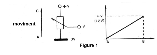
The movement of the cursor is done precisely by a mechanical system in which the force of the competitor must be applied. Details of this system using a lever and spring are given below, but we can tell you that the higher the force applied, the greater the displacement of the slider and, therefore, the greater the voltage obtained at the output.
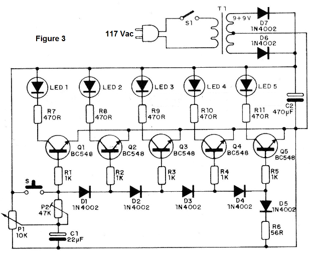
To indicate this voltage, which is proportional to the force, we have a configuration, which corresponds to the second block.
In this circuit we use a sequence of diodes and transistors connected in such a way as to have a progressive conduction that is a function of the input voltage and consequently of the force.
In this circuit, when applying a low voltage only the first diode is able to conduct the current and consequently only the base of the first transistor receives polarization in the sense of making the first LED light up.
If we increase the voltage, more diodes are able to conduct and, progressively, more transistors are polarized in the sense of making the corresponding LEDs light up.
As each diode requires a voltage of the order of 0.6 V to drive, this system operates in steps of approximately 0.6 V.
See, in practice, we also have that the base-emitter junction of each transistor is a diode, which allows us in the final assembly to eliminate the first diode.
In order for the device to function exactly as expected, i.e., no LED lights up without force, and all at the end, there is a setting that is nothing more than a potentiometer (P2) connected in series with the input.
See that the number of LEDs could be increased, but this also means the need to increase the supply voltage, so the practical design limit is around 8 to 9 of these LEDs.
The resistors in series with the LEDs determine their brightness and function of the supply voltage. Using a 12 V transformer, for example, for a magnification of 7 or 8 LEDs, the resistors must be increased to 1 k.
ASSEMBLY
We must separate the mechanical part of the electronic part, as this is very important in this project, and details are needed to facilitate its execution.
Then we have in Figure 2 the sensor that requires skill with tools for carpentry.
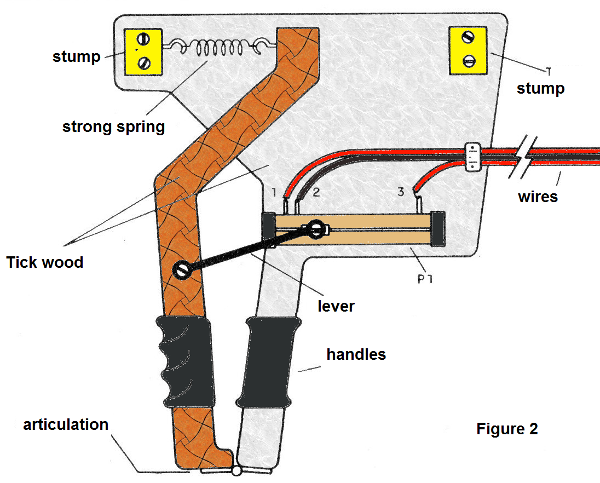
The base is made of wood and there are some resistant metal parts which should withstand the full strength of the competitor. The stubs, which form the spring support and the limit of the cursor, must be approximately 2 cm thick and are fixed by screws. See that the set must support all the force that will be applied by the competitor, which means that the base must be of thick wood.
The spring is one of the main elements of this assembly, because it is its tension that determines the force we can apply to the device. A strong spring, of the type we used in gates, must be chosen according to the "musculature" of the competitors.
If the spring is weak, simply increase the distance proportionately (a).
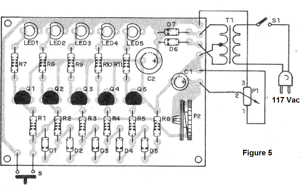
For the electronic part, we begin with the complete diagram of the apparatus given in Figure 3.
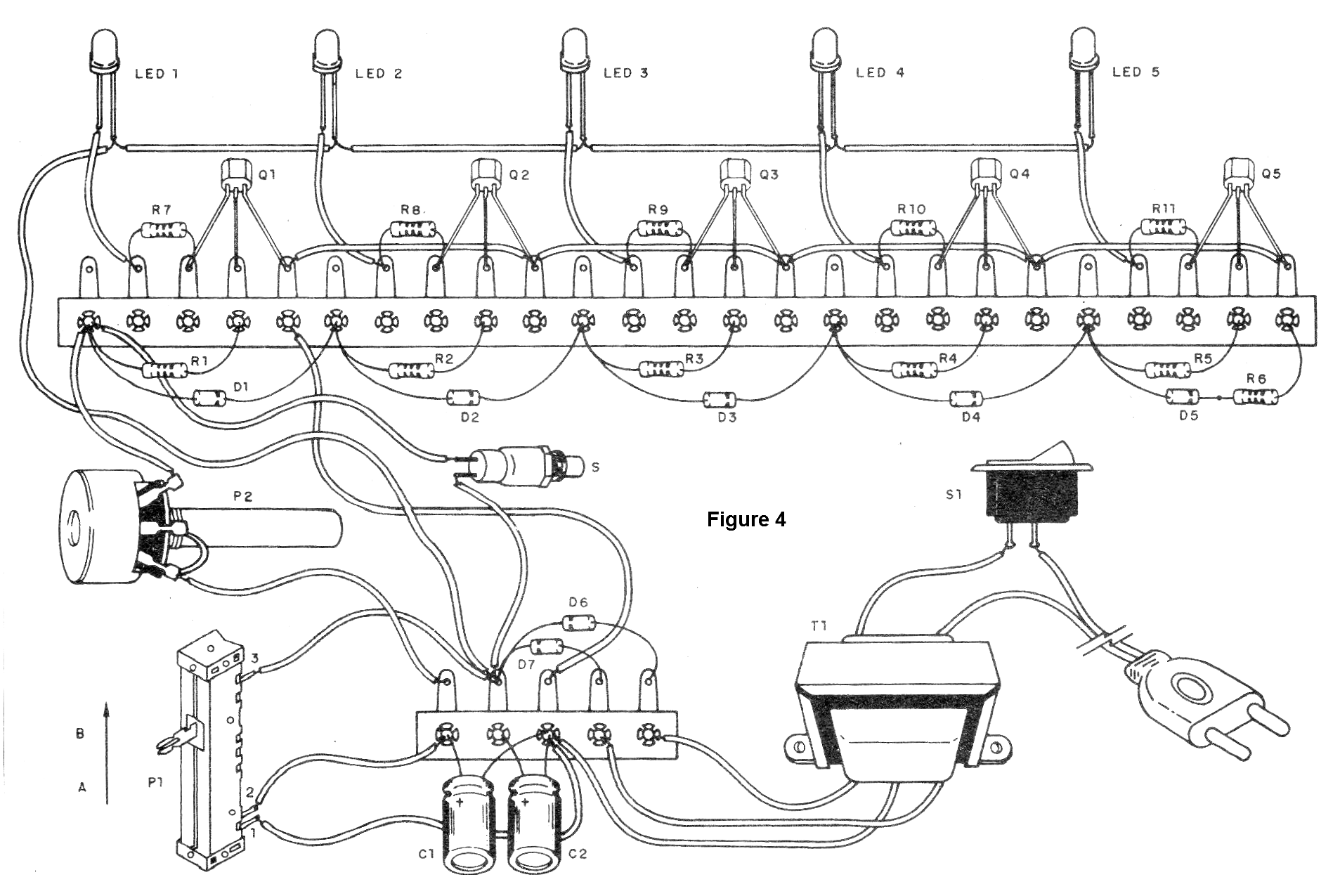
The terminal of bridge assembly is shown in Figure 4.
 Click for amplifier
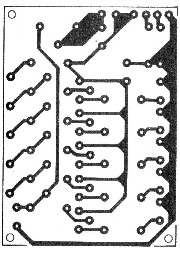
For those who want a printed circuit board version, we give their life-size drawing in Figure 5.
The following are the main precautions that should be taken with this assembly:
A) Start with the welding of all transistors that can be type BC548 or equivalent such as BC237, BC238, BC547 etc. Observe their position;
B) Then, weld the LEDs, considering that these components have the position given by the flat part, which corresponds to the cathode. One reversal and the LED does not light;
C) The diodes can be 1N4002 or lower cost equivalents such as 1N4148, 1N914 etc. Note also the polarity given by the stripes on the enclosure;
D) The resistors are all 1/8 or ¼ W, depending on availability, and their values ??are given by the colored stripes according to the material list;
E) The two capacitors used are electrolytic 25V working voltage - their polarity must be observed in the assembly;
F) For the power supply the transformer can be 9 + 9 V, with at least 200 mA of current, or 12 +12 V for a greater number of LEDs, with at least 250 mA of current;
G) P1 is a slide and its value is not critical, being between 4k7 and 22k. P2 is 47k or the trimpot is of the same value. At the P1 connection it is very important to observe the connection order so that there is no "reverse" operation of the device.
We also have additional components such as S, which is a pressure switch that is to test the operation and the S1, which is a simple switch to switch the appliance on, power cord and source diodes that are 1N4002 or equivalent.
TEST AND USE
Switch on the appliance and first let P1 at the position of minimum effort.
Set P2 so that the first LED is about to light up. Then, by pressing the "trigger" of the sensor, make a new adjustment so that, at maximum force, all LEDs light up.
To show a suspicious competitor that all the LEDs light up, simply press S.
If the last LED does not light up (LED 5), or you cannot achieve an adjustment as expected, connect a 47k resistor in series with P2, or change it to a higher value (100k or even 220k).
If any LEDs do not light up, check if it is not upside down.
If it is correct, momentarily short circuit the collector to the transistor emitter. If the LED lights up it is because the transistor is bad, otherwise the LED should be replaced.
Q1 to Q5 - BC548 or general purpose NPN transistor equivalents
D1 to D7-1N4002 or general purpose diodes equivalent
LED1 to LED5 - common LEDs
T1 - Transformer with primary according to the local and secondary network of 9 + 9 V with at least 200 mA current
C1 - 22, uF x 25 V - electrolytic capacitor
C2 - 470 uF x 25 V - electrolytic capacitor
P1 - 10k - sliding potentiometer
P2 - 47k - trimpot or potentiometer
S - Pressure switch
S1 - Simple switch
R1 to R5 - 1k x 1/8 W - resistors (brown, black, red)
R6 - 56 ohms x 1/8 W - resistor (green, blue, black)
R7 to R11 - 470 ohms x 1/8 W- resistors (yellow, violet, brown)
Miscellaneous: printed circuit board or terminal bridge, mechanical part, assembly box, power cable, wires, welding etc.


