

When light strikes a sensor the circuit triggers and produces an intermittent tone in a good piezoelectric buzzer or transducer. What can be done with it? If this is the question you ask even though we have seen our introduction, without finding any use for the circuit yet, then you certainly lack a little imagination.
Some possible applications for the appliance are given below.
* Leaving it on a table, at night, if someone enters the room and turns on the light or even inadvertently illuminates the room with a flashlight (in the case of a thief) the alarm goes off. He may serve to warn you of the late arrival of a disobedient son, catching him "on the jump" for a "good fight"!
* Next to a window, it will warn you when dawn triggering with the dawn, like a solar alarm clock. It can also be used to detect lightning flashes, warning you of the need to close a window or collect something that has been left out.
* In a dark environment, it can fire if any flame appears, thereby detecting a fire start.
* In the workshop we can use it to detect the activation of indicator lights of a panel when we are in an unfavorable position for its visualization.
Anyway, the applications of our alarm depend exclusively on imagination and for this there are no limits.
Characteristics:
* Power supply voltage: 6 to 9 V
* Current at rest: less than 1 mA
* Trip current: 5 mA 9-bit)
HOW IT WORKS
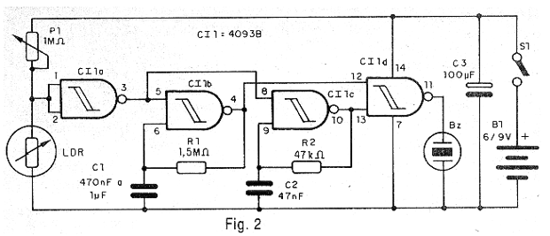
Once again, in alarm designs, we use the 4093B integrated circuit which, because of its versatility and low cost, offers the best practical solutions. This integrated circuit consists of 4 2-input NAND trigger ports that can be used independently. The first one (CI-1a) is connected as a simple inverter, being driven by the circuit sensor consisting of a common LDR. P1 makes the setting of the trigger point and hence the sensitivity.
This way, in the dark when the LDR is with its high resistance, the input of the inverter stays in the high level and with that its output in the low level. With the low level output, the second block of the apparatus consisting of two oscillators with the CI-1b and CI-1c ports remains disabled.
The oscillators in question operate at different frequencies. The first, formed by CI-1b operates at a very low frequency, hertz fraction, so as to generate beeps that will modulate the final sound. The second operates at an audio frequency of the order of 7 kHz which corresponds to the highest yield point of most ordinary ceramic transducers.
In this way, when there is light in the LDR, the voltage level at the input of the CI-1a port changes to be interpreted as low, which leads to the high level output, triggering the two oscillators. Its signals are then combined in the fourth circuit port (CI-1d) which then delivers, at its output, to the transducer, paced beeps.
The transducer used may be of ordinary piezoelectric type without oscillator or even a crystal microphone capsule or even a piezoelectric tweeter from which the small internal transformer has been withdrawn. However, if the reader wants a more intense tone, we have in Figure 1 two high-intensity power circuits that can be added to the original design.
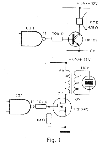
The first makes use of a common speaker and the power of the circuit can be made with voltages up to 12V. The transistor, however, must be mounted on a heat radiator. Note that in this version as well as the next, the current consumption increases in the touch, requiring a slightly more powerful source like battery, medium or big batteries.
The second version makes use of a power FET and a transducer that will be powered with a voltage that can surpass the 300 V. This causes that it produces a really intense sound. A piezoelectric tweeter can be used without the transformer in this version.
ASSEMBLY
In figure 2 we have the complete diagram of the apparatus.
The arrangement of the components on a printed circuit board is shown in figure 3.
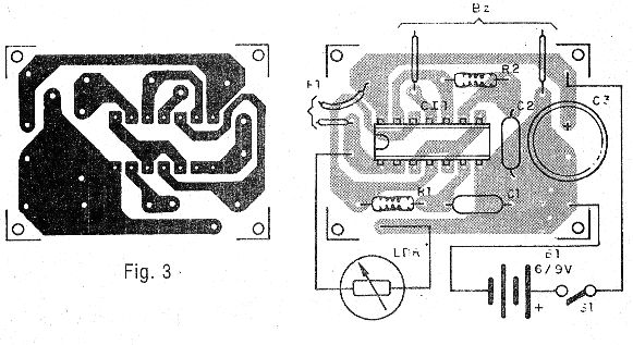
For the integrated circuit we suggest the use of a 14 pin DIL socket. The LDR is ordinary round type 1 or 2.5 cm in diameter. Any type is suitable, including those used for older televisions that have automatic brightness control. The transducer is nothing more than a piezoelectric capsule, including headphones or microphones or even a piezoelectric tweeter from which the small internal transformer has been removed.
For powering the basic version we can use batteries or battery and the potentiometer P1 can be replaced by a trimpot so as to obtain a more compact unit.
Test and Use
To test the unit, place it in a dim light and, after turning on the power, set P1 so that it does not produce any sound. Turn on ambient light or let more light in. The alarm should sound.
To use the unit, simply leave it in a dimly lit location but receive the light from the environment if someone enters the room or turns on the main light.
To detect an indicator light on a panel, simply point the LDR at the location. For this it must be mounted on an opaque tube. P1 is then set so that there is no sound when the light is off.
Semiconductors:
CI-1 - 4093B - CMOS integrated circuit
Resistors: (1/8 W, 5%)
R1 - 1.5 M ohm
R2 - 47 k ohm
P1 - 1 M ohm - potentiometer
Capacitors:
C1 - 470 nF - polyester or ceramic
C2-47 nF - polyester or ceramic
C3 - 100 uF / 12V - electrolytic
Miscellaneous:
LDR- Photo-resistor common LDR
BZ - Piezoelectric transducer - see text
S1 - Single switch
B1 - 6 or 9 V - 4 batteries or battery
Printed circuit board, mounting box, potentiometer button, battery holder or battery connector, wires, solder, etc.


