

The circuit can be powered from 6 or 12 V supplies, depending on the relay. Do not use transformer power supplies in this project, as they may lead to shock or dangerous situations.
Sensitivity can be increased by connecting point X to a good earth.
Cx is used if the circuit tends toward erratic operation due to signals picked up by the sensor or its wire.
A schematic diagram of the Touch Switch is shown in Fig. 1.
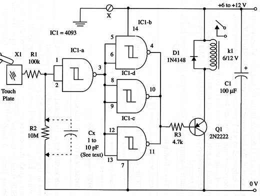
Figure 1 – Schematic diagram of the Touch Switch
The touch sensor is a 2 X 2 inch metal plates and is connected to the circuit by a 4 to 10 inch common wire.
Sensitivity can be changed by altering R2. Values between 2 M ohm and 10 M ohm can be used experimentally.
IC1 - 4093 CMOS integrated circuit
X1 - sensor plates (see text)
Q1 - 2N 2222 N PN general purpose silicon transistor
D1 - 1N4148 general purpose silicon transistor
K1 - 6 or 12 V relay (see text)
R1 - 100,000 ohm, 1/4 W, 5% resistor
R2 - 10,000,000 ohm, 1/4 W, 5% resistor
R3 - 4,700 ohm, 1/4 W, 5% resistor
CX - See text
C1 - 100 µF, 16 WVDC electrolytic capacitor


