
Of course a quake detector does not exclusively detect earthquake or deep-water tremors. The passage of a truck, an underground explosion or even a strong blow on the ground is enough to produce a shockwave that will trigger the apparatus we describe.
If you need something that detects this kind of low-frequency vibration and spreads through the ground then you will surely be satisfied with the project we will describe.
Powered by batteries, this system can activate a relay that is used to power any warning device.
The circuit is simple, has low power consumption in the standby condition and the sensor, while requiring some mechanical ability for its construction, employs absolutely common materials.
How it works
The sensor consists of a coil with many turns of fine wire that has placed in the around a magnet in a mobile system with a pendulum, as shown in Figure 1.
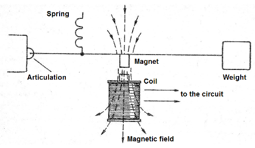
Any kind of vibration that reaches the pendulum and makes it sway, even if imperceptibly, will cause the magnet to induce an electric tension in the coil.
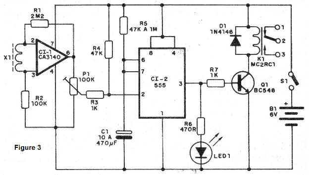
This voltage will be applied by an ultrasonic operational amplifier with field effect transistor at the input. This CA3140 has its gain controlled by the resistor R1, being in the indicated condition very close to its maximum.
The output of this operational amplifier is used to trigger, via an adjustable trimpot, a monostable with the 555 integrated.
This monostable has its output time determined by the capacitor C1 and the resistor R5 which can be varied between 47k and 1M. The capacitor, with a value of 100 uF, allows the ringing of the alarm to last for some tens of seconds. The maximum allowed C1 value is 470 u F.
At the output of the 555, we have an LED indicator and the activation system of the relay with a BC548 transistor.
The power for all stages of the circuit comes from a 6 V source made of common batteries. For a domestic operation, a regulated source with the integrated 7806 can be used, as shown in Figure 2.
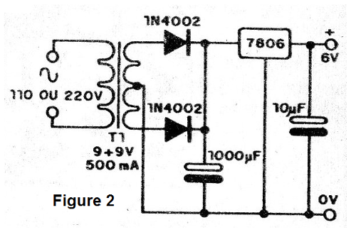
The integrated source must have a small radiator and electrolytic filtration of at least 1 000 uF by 16 V.
ASSEMBLY
In Figure 3 we have the complete diagram of the seismic alarm.
The project execution on a printed circuit board is shown in Figure 4.
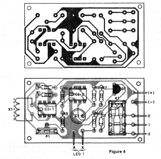
The relay used, of the sensitive type of 6 V, has two contacts for 2 A with positions NO and NC (normally open or normally closed), which allows the use of the device in several ways.
The integrated ones must be built in sockets for greater safety and the resistors are all 1/8 or ¼ W with any tolerance.
For the sensor we have an assembly as shown in Figure 5.
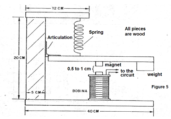
The weight used should be around 100 grams and the magnet is removed from a small speaker or DC motor of some toy or even from a lock of cabinets.
The coil is the primary winding of a 110/220 V transformer with any secondary from 200 to 500 mA. We take the core carefully and use the reel.
The magnet must then be built close to the coil which, for greater sensitivity, will have a piece of ferrite in it.
The connection cable from the sensor to the circuit input should be double-shielded, as the system is extremely sensitive to the captation of alternating current grunts and even the induction of nearby magnetic fields. This double wire must have the grounded wire (connected to the negative of the source), because otherwise a lightning storm can trigger the system.
The spring must be chosen in order to give a good flexibility to the system and its positioning depends precisely on its tension.
In Figure 6 we give a simple alarm circuit which eliminates the necessity of the relay, since it can be activated directly by the high level in the output of the 555.
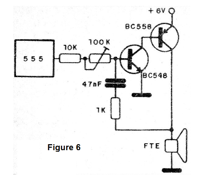
This 6 V power supply circuit and a good performance speaker produces a loud sound to catch the attention of people within a few tens of meters.
The trimpot allows you to adjust the frequency of the sound. (Figure 6)
For greater sound intensity this circuit can be powered with a voltage of 12 V.
In this case, simply change the resistor in series with the LED to 1k or 1k2 and change the transistor from the output of the audio oscillator, a BC558 to a BD136 or TlP32, which should be equipped with a small heat radiator. All the other components of the circuit remain unchanged.
TEST AND USE
To prove it is convenient to initially use for C1 a capacitor of only 10 uF or less.
This will have smaller trigger times, thus facilitating the placement of P1 at the ideal trigger point.
Then we proceed as follows: we turn on the unit and if it triggers we act on P1 until it turns off. The action of P1 is not immediate because it depends on the time constant given by C1 and the resistor R5.
With the system off, let's open P1 until we get the trigger. We then turn this component a bit to bring it to the threshold of the circuit activation.
After that, we tap on the table where the sensor is or on the pendulum itself, which should then activate the trigger.
Once the operation is verified, we can change C1 to a higher value capacitor if it is desired.
Note that the pendulum is placed in order to detect oscillations that arrive vertically on it, as shown in Figure 7.
Another type of configuration shown in the same figure allows to detect with greater sensitivity seismic waves which have other ways of propagation.
If several sensors are used, they can be connected in series or even in parallel to the input of the CA3140 operational amplifier, because it has good sensitivity and there is no loss of gain.
After all this the unit is ready to go. A practical hint of employment for a device such as this in a country without earthquakes is as an alarm with the sensor attached to a window, it can detect an attempt of break-in or beats that aim to break it, the same happening on doors.
In a car, if someone forces a door or even sit on the seat, the swing will trigger the system which is hidden, for example, in the trunk, can fire the horn.
MATERIAL LIST
Cl-1 - CA3140 - Integrated Circuit Operational Amplifier with FET at the Input
CI-2 - 555 - timer - integrated circuit
Q1 - BC548 - NPN general purpose transistor
X1 - sensor (see text)
K1 - 6 V relay
LED1 - Common red LED
D1 – 1N4148 - general purpose diode
C1-22 to 470 uF - electrolytic for 6 V or more
R1 - 2M2 - resistor (red, red, green)
R2 - 100k - resistor (brown, black, yellow)
R3 - 1 k - resis (brown, black, red)
R4 - 47k - resistor (yellow, violet, orange)
R5 - 47k at 1 M - resistor (higher value longer time)
R6 - 470 ohm - resistor (yellow, violet, brown)
R7 - 1k - resistor (brown, black, red)
P1 - 100 k - trimpot
B1 - 6 V - 4 small, medium or large batteries
S1 - single switch
Miscellaneous: printed circuit board, sensor material, battery holder, integrated sockets, LED holder, assembly box, wires, shielded cable, welding, etc.


