The basic version triggers a relay from an audio tone that is transmitted through any of our initial projects.
What we are going to control depends exclusively on the power of the relay.
The great advantage of this circuit is that we can take advantage of the sensitivity and selectivity of commercial receivers in our projects, which are usually much better than that of super-regenerative receivers. There are even ultraminiaturized versions in watches or toys that could easily be adapted to a remote control.
We note that these receivers may also have their outputs directly connected to the filters described in the previous assembly for the realization of a multi-channel system.
THE PROJECT
The circuit consists of a sensitive two-transistor adapter stage that receives signals from the receiver's audio output, for example, the handset or speaker output, and after rectification and filtering by D1 and C1, amplifies them with transistors Q1 and Q2 to relay excitation.
The circuit is very sensitive operating with signals even from receivers for headphones only.
The 6 V supply of the circuit can be independent, formed by 4 small batteries or taken advantage of the own receiver with which it operates.
ASSEMBLY
In figure 1 we have the complete diagram of the driver.
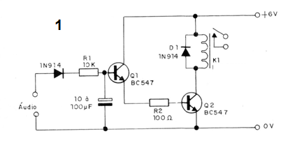
Figure 2 shows how to place the components on the printed circuit board.
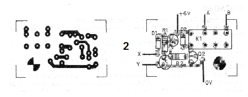
The 6 V relay can be installed in a 16-pin DlL socket used for integrated circuits.
The resistors are 1/8 W and instead of the original transistors can be employed equivalent.
The electrolytic C1 determines the speed of response and the noise immunity of the system and its value must be obtained experimentally in the indicated range.
For higher frequencies of modulation the immunity decreases and the capacitor can be further reduced.
PROOF AND USE
Initially tune the receiver to the frequency of any of the tone modulated transmitters we describe in this book.
Then connect the driver to your headphone jack or to the speaker (which can be initially held in the circuit).
At each touch of the transmitter the relay must be triggered.
Checking that the device works properly and only installing it on what you want to control at a distance. Performance depends on receiver sensitivity and transmitter power.
SEMICONDUCTORS
Q1 and Q2 - BC548 or equivalent - general purpose transistors
D1 and D2 - 1N914 - silicon diodes
RESISTORS
R1 - 10 k ohm (brown, black, orange)
R2 - 100 ohm (brown, black, brown)
VARIOUS
K1 - 6 V relay or equivalent
Printed circuit board, socket for integrated circuit, wires, solder, etc.