

The circuit is sensitive and can be powered with the 6 V external batteries or the receiver's own power to operate it.
The audio signal for the trip can be taken from the handset or speaker output of the receiver.
THE PROJECT
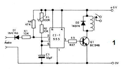
The design basis is a monostable with the integrated circuit 555 and has its timing determined by the values ??of P1 and C1 For longer times these two components can be increased, going from C1 up to 1000 uF and P1 up to 2M2, in which case will exceed half an hour.
The audio signal is rectified by D1 and bounded by R1, and is then used to trigger monostable by pin 2.
When the integrated is tripped, its output goes to the high level, polarizing Q1 that energizes the relay for the time determined by the P1 setting.
At the end of the time, the relay is de-energized because the output of the integrated circuit returns to the low level. For a new trigger, new short-term audio signal must be applied to the input.
The sensitivity of the circuit is good and it can be turned on at the output of small FM receivers. In some cases it may be necessary to add a capacitor of 10 to 100 uF between the diode D1 and the output of the receiver.
ASSEMBLY
In figure 1 we have the schematic diagram of this timed drive module.
The arrangement of the components based on a printed circuit board is shown in figure 2.
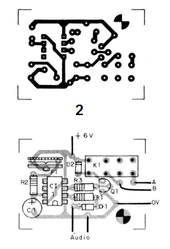
The integrated circuit and relay can be installed in a 8 or 16 pin DIL socket.
The resistors are for 1/8 watt dissipation and the electrolyte is for 12 V.
Power may come from a set of batteries or from the receiver itself.
that the module will work.
The diodes accept equivalents as well as the transistor.
USE
To test the instrument, proceed as indicated in the two previous projects by setting P1 to the shortest time. For each audio tone of the transmitter the relay must close its contacts and thus remain for a time which depends on the setting of P1 and the value of C1.
Checking that the operation is normal is only to make the final installation of the device in the one to be controlled, respecting the maximum current of the contacts of the relay.
SEMICONDUCTORS
CI-1 - 555 - integrated circuit
Q1 - BC548 or equivalent - general purpose NPN transistor
D1, D2-1N4148 or 1N914 diodes of general use
RESISTORS
P1 - 100 k at 1M (trimpot)
R1 and R2 - 10 k ohm (brown, black, orange)
R3 - 4k7 ohm (yellow, violet, red)
R4 - 47 k ohm (yellow, violet, orange)
CAPACITORS
C1 - 10 uF (electrolytic)
--VARIOUS
K1 - 6 V relay
Printed circuit board, DIL sockets for integrated and relay, wires, solder, etc.


