
This article is from 1987. More modern versions can be found on the website. However, the components for this release are still common.
The stroboscopic effect occurs when two phenomena which repeat themselves at certain frequencies overlap. The result is an effect composition that can result in the stoppage or reversal of movement of one of them.
An example of this can be seen in TV movies in which carriage wheels appear. The rotational movement of these wheels combines with the film's motion or image transmission from the TV make us have the feeling that the wheels spin back or even stop.
If you turn a small paper propeller in front of the TV, as shown in Figure 1, you can achieve the same effect.

The speed of reproduction of the frames of the TV (analog) combines with the rotation of the propeller and we have the sensation of an interrupted movement, or of a movement which is paralyzed or inverted.
With any type of lighting which occurs at a certain frequency, the movements can suffer the same effects and this is the principle of our strobe light.
We make one or more ordinary lamps flash at a relatively low frequency, between 0.5 and 2 Hz, so that the movements of the illuminated persons are interrupted. The effect is interesting in the case of dances, as these movements seem to occur at "jumps".
The device is simple, uses few components and is powered directly by the power grid.
THE CIRCUIT
What we have is a relaxation oscillator with neon lamp which directly shoots an SCR of type MCR106 or TIC106.
This SCR controls an ordinary 5 to 100 watt incandescent bulb.
Ordinary incandescent (filament) lamps have a certain inertia, so that they cannot flash at high frequencies, but only a maximum frequency of 2 Hz is sufficient for the desired effect.
The blinking frequency depends on the setting of P1 and the value of C1.
We use for P1 a potentiometer of 1M and for C1 a polyester capacitor whose value must be between 1 and 5.6 uF. The working voltage of this capacitor must be at least 100 V.
The higher the capacitor, the slower the blinks and the stronger. Our recommendation, for better effects, is that the capacitor used is the greatest one. The smaller values work as an alternative if the 5.6 uF is not found.
ASSEMBLY
In Figure 2 we have the complete diagram of the strobe light.
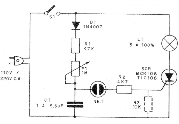
Note that R3 is optional: this component should only be used if SCR is TlC106. For MCR106 it is not necessary.
The assembly based on a terminal bridge is shown in Figure 3.
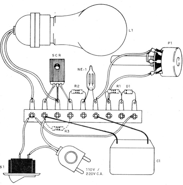
SCR must be fitted with a small heat radiator, which is not shown in the bridge design.
This radiator consists of a "U" folded metal plate that is attached to SCR itself by means of a bolt with a nut.
In place of an incandescent lamp, several can be supplied, connected as shown in Figure 4.
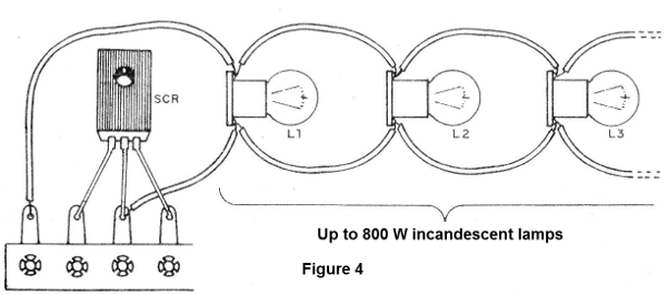
At the 110 V network the total number of lamps should not exceed 300 watts and at the 220 V network should not exceed 600 W for MCR106. For TlC106 we have 400 W at 110 V and 800 W at 220 V.
Note, however, that SCR is a half-wave control so the blinking will not be strong, i.e., it will not have the maximum lamp power but half of it. This factor is important even for the lamp durability, since an excessive and variable current besides the temperature shocks it could burn the lamp in a short time.
The capacitor C1 is of an unusual type in the market. It is a 100 V polyester capacitor with 5.6 uF. If the reader does not find this component, there are several possibilities. One of them is connected to 2 parallels of 2.2 uF or even 4 of 1 uF. Another experiments with smaller values ??and adjust the system at P1.
The neon lamp is of type NE-2H with two parallel terminals and without internal resistance.
The resistor R2 can eventually be changed (more or less), thus modifying the flashing energy as a function of the capacitor.
The diode D1 supports some equivalents. For the 110 V network, 1N4004, BY126 or BY127 can be used. BY127 can be used for the 220 V network.
TEST AND USE
To test, we only need to connect the unit to a power grid. By adjusting P1 we should get rhythmic flashes quickly.
If the remaining lamp keeps on directly at any point of the adjustment but the neon lamp flashes, we have two possibilities: the R3 resistor has not been used and needs to be used, or the SCR is burnt.
To use it, we just need to install the lamp in a dark place, at a dance floor. The number of lamps, within the limits indicated above, will depend on the size of the room.
The installation in a plastic or metal case will facilitate the use and transportation of the device.
SCR - MCR106 or TlC106 - see text
D1 - 1N4007 - rectifier diode
NE-1 - neon lamp
S1 - Single switch
P1 - 1M - lin or log single potentiometer
R1 - 47k x 1/8 W - resistor (yellow, violet, orange)
R2 - 4k7 x 1/8 W - resistor (yellow, violet, red)
R3 - 10k x 1/8 W - resistor (brown, black, orange)
C1 - 1 to 5.6, uF X 100 V - polyester capacitor (see text)
L1 - 5 to 100 watts - 110 volt common lamp or. 220 V according to the local network - see text
Miscellaneous:
terminal bridge, power cable, button for P1, wires, socket for the lamp, etc.


