
A good inverter for powering fluorescent lamps can be made based on powerful transistors, but usually the modulation of these inverters for the production of flashes leads to some additional problems.
In this paper we have described a simple solution to obtain high voltage trains for feeding a fluorescent lamp with good efficiency using only an integrated circuit and a Darlington transistor.
The end result is an excellent battery-powered signaling device and compact enough to be installed in a small plastic housing.
Another imgateant feature of this type of circuit lies in the fact that used lamps need not be new.
Even weak light bulbs, which no longer light up in ordinary household installations, may shine brightly in this circuit thanks to the high voltage peaks that the circuit produces.
HOW IT WORKS
A small transformer used in the voltage boost needs to be fed with a relatively high frequency signal for good performance.
We choose the frequency of approximately 800 Hz in our case and from there we elaborate the excitation circuit.
Thus, we have two oscillators made based on the trigger gates of an integrated CMOS 4093 and having the configuration shown in figure 1.

The first gate is used as a fixed frequency oscillator of approximately 800 Hz.
This frequency is given by R1 and C1. The second oscillator has a much lower adjustable frequency, and operates between 0.1 and 4 Hz.
This second oscillator will be responsible for the signaling flashes.
The frequency of the second oscillator is basically given by C2, R2 and P1, the latter being used in its adjustment.
The signals of the two oscillators are combined in a third gate thereof integrated so as to obtain pulse trains as shown in figure 2.

The low-voltage rectangular pulses obtained from this gate are applied to the base of a Darlington type TlP120 power transistor.
The load of this transistor, attached to its collector is the low voltage winding of a small 220V primary power transformer.
In the primary winding will be connected the fluorescent lamp that can have powers in the range of 7 to 40 W.
The power of the circuit is only a few watts, which means that the larger bulbs will light up with less brightness.
To protect the circuit in case of short, an input fuse is used.
With a 12 V supply, we get the optimum performance of the circuit, but in some cases it will also operate with lower voltages such as 9 V and even 6 V, in which case it can be used with batteries, but the brightness of the fluorescent lamp will also be smaller.
An interesting suggestion to obtain dual function of this circuit is to add a small switch that disconnects the pin 9 from the integrated 4 of the same component and make its permanent connection to the (+) of the power supply.
This will light the lamp continuously and the device will become a simple inverter for fluorescent lamps.
ASSEMBLY
In figure 3, we show the complete diagram of this inverter.

The printed circuit board is shown in figure 4.

We suggest the use of a socket for the integrated one, to avoid heat at the time of welding.
The TlP120 transistor must be equipped with a small heat radiator.
The capacitors C1 and C2 may be polyester or ceramic, while C3 may be an electrolyte for 12 V or more.
The resistors are all 1/8 or ¼ W and P1 is a common trimpot.
Appropriate supgate must be used for the fuse, and the T1 transformer is not critical since 7.5 or 9 V substations also fit and the currents can be in the 500 mA to 1 A range.
The assembly can be installed in a plastic box as shown in figure 5.
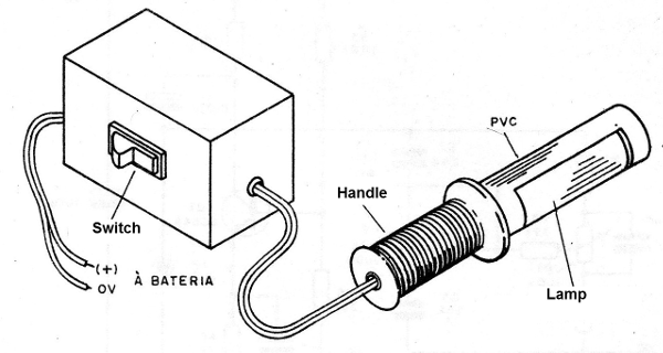
For the connection the lamp must be used wired wire since the high tension present can cause unpleasant shocks.
TEST AND USE
To test the device simply connect it to a 12 V power supply with at least 1A of current capacity.
P1 is set to blink at the desired pace. These blinks are accompanied by a small buzz in the transformer.
If humming occurs, but the lamp does not light, check the lamp status that may be too weak even for this application.
The connecting cable to the fluorescent lamp can be long, up to 10 meters and for connection on the battery we suggest the use of different colored claws.
Be careful of polarity at the time of connection.
CI-1 - 4093 - integrated circuit
Q1 - TIP120 - Darlington NPN transistor
F1 - 2A - fuse
T1 - Transformer with primary of 220 V and secondary of 6 + 6 V with 500 mA.
X1 - 7 to 40 W Fluorescent Lamp
P1 - 4M7 trimpot
R1 - 47 k x 1/8 W - resistor (yellow, violet, orange)
R2 - 1 M x 1/8 W - resistor (brown, black, green)
R3 - 2k2 x 1/8 W - resistor (red, red, red)
C1 - 22 nF - ceramic or polyester capacitor
C2 - 470 nF - ceramic or polyester capacitor
C3 - 100 uF x 15V ~ electrolytic capacitor
Miscellaneous: printed circuit board, mounting box, integrated socket, fuse holder, connector for fluorescent lamp, wires, solder, etc.


