ART558S
The tone controls are usually added to the preamplifiers in the most elaborate projects hence the fact that most power amplifier circuits do not feature this feature.
However, many readers sometimes depart from a power amplifier as something definitive that they will use immediately when they then feel the lack of a tone control.
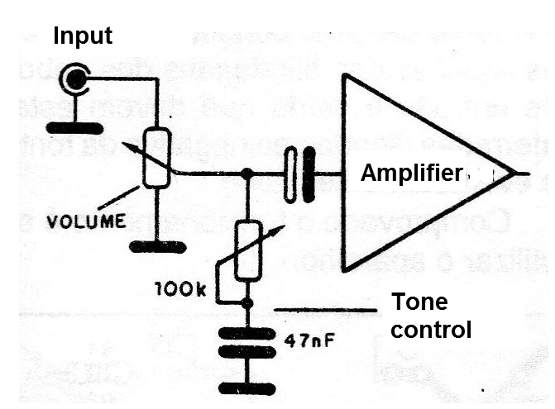
A simple but not very interesting version is the one that makes use of passive components, a kind of low pass filter, as shown in figure 1 that before attenuates the treble of that reinforces, the bass which can bring inconveniences the final quality of the audio .

The ideal for a simple amplifier design is a Baxandall type universal tone control that has a certain gain in order to compensate for losses in the system itself.
The circuit we present uses a single general purpose transistor and has a sensitivity that allows its operation with signals of the order of 200 mV when we then have a low distortion rate.
Power in the 9 to 18 V range can be used in the amplifier itself since the drained current does not exceed a few milliamps.
THE CIRCUIT
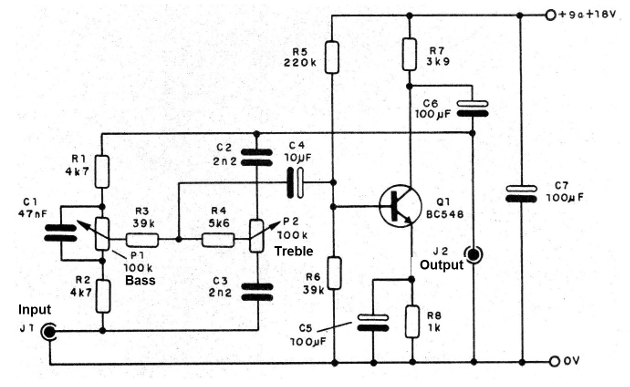
The tone control is of the Baxandall type where the feedback is drawn from the collector circuit of the transistor through C6 being applied to the base of the transistor via C4.
The resistors R5 and R6 set the operating point of the transistor and may be altered depending on the characteristics of the signal source.
The transistor operates on the common emitter configuration which provides a good gain, although the input impedance is not very high.
However, conventional signal sources such as phonographic capsules, small mixers, radios, etc. can perfectly excite this circuit which may even provide an increase in sensitivity over many power amplifiers.
ASSEMBLY
In figure 2 we have the complete tone control circuit.

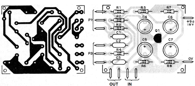
The arrangement of the components on a printed circuit board is shown in figure 3.

Remember that signal cords must be all shielded so that there is no buzzing, which is also true for the connection of the tone control potentiometers.
The resistors are all 1/8 or ¼ W with 10 or 20% tolerance and the smaller capacitors can be polyester or any type recommended for audio.
The electrolytes are for 25 V or else a slightly higher working voltage than is intended for use in the power supply.
The control can be installed in the housing of the amplifier itself, or in its own case, which should preferably be metallic to serve as a shield.
The input jacks are according to the signal sources normally used (RCA, for example). The output can be eliminated if the unit is connected directly to the amplifier circuit.
For a stereo version, equal units must be mounted with double-pitch potentiometers, so that there is simultaneous operation on both channels.
TEST AND USE
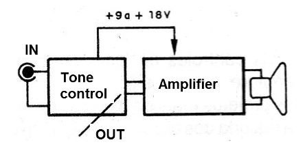
The tone control is interleaved between the signal source and the amplifier input as shown in figure 4.

If there is a snoring when there is no signal source connected, check the cable connections of the input and output cables that must be grounded (connected to the negative of the source and possibly the box).
Q1 - BC548 or equivalent - general purpose NPN transistor
P1 and P2 - 100 k - linear potentiometers
R1 and R2 - 4k7 - resistors (yellow, violet, red)
R3 - 39 k - resistor (orange, white, orange)
R4 - 5k6 - resistor (green, blue, red)
R5 - 220 k - resistor (red, red, yellow)
R6 - 39 k - resistor (orange, white, orange)
R7 - 3k9 - resistor (orange, white, red)
R8 - 1k - resistor (brown, black, red)
C1 - 47 nF - polyester capacitor
C2 and C3 - 2112 - polyester capacitor
C4 - 10 uF - electrolytic capacitor
C5, C6 and C7 - 100 uF - electrolytic capacitors
J 1 and J 2 - input and output jacks - see text
Miscellaneous: printed circuit board, buttons for potentiometers, shielded wires, mounting box (optional - see text), fastening screws, nuts, solder, etc.


