This circuit is based on an LDR that senses ambient light variations by transferring a command to a triac that controls a lamp from 5 to 400 watts.
An adjustment of the operating mode allows the lighting to be conditioned at the highest and lowest level depending on the lighting.
The circuit can operate in both the 110 V and 220 V networks and is quite compact, and can be installed in a small plastic box.
How it works
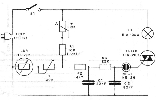
The Triac operates as a power control, allowing more or less current to pass through to the lamp according to the excitation of its gate.
This excitation comes from a neon lamp that shoots at different angles of conduction of the alternating current, according to the double time constant given by C1 and C2.
P2 then sets the maximum excitation level, ie the maximum current that passes the lamp in the absence of illumination, when the LDR resistance is higher.
The LDR acts as a bypass resistor for the tripping voltage of the neon lamp, thereby delaying the triac's conduction point.
With low resistance (LDR illuminated) the neon lamp only leads at the end of the half-cycle, so that the trip of the triac becomes well delayed leaving the lamp a small current.
With the LDR in the dark the voltage is applied to the lamp quickly and the firing is done at the beginning of the half-cycle, with more current being driven.
P1 allows you to adjust the performance of the LDR depending on the ambient light and its variations.
The resistor R1 should be 22 k if the supply voltage is 220 volts.
An interesting possibility of altering this assembly is to use a diac instead of NE-1. In this case, probably C1 and C2 must be changed to obtain the new trigger range.
Assembly
In Figure 1 we have the complete diagram of the system

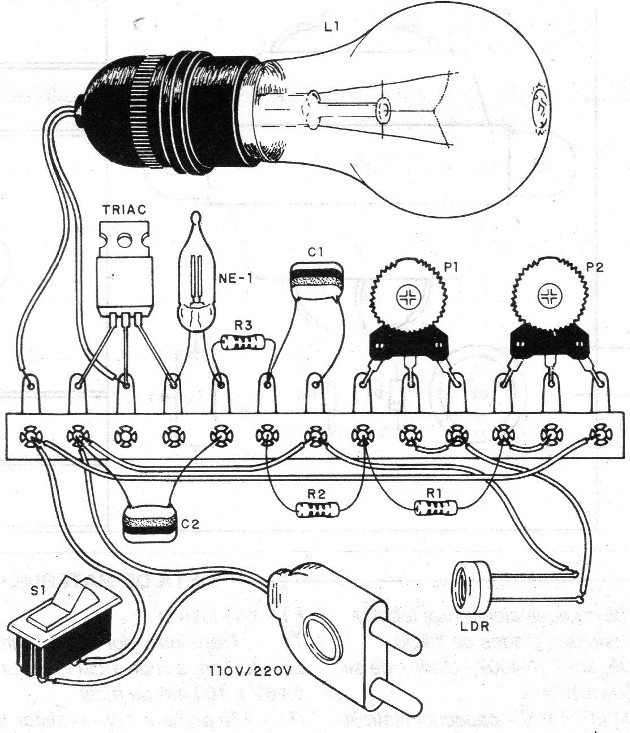
Since it is a simple assembly that is indicated to the beginner, we first give the terminal strip version, shown in figure 2.

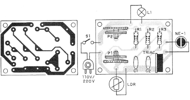
In figure 3 we have a suggestion of printed circuit board.

The LDR used can be of any type. This LDR must be installed so as not to receive light from the lamp it powers. If this occurs, we will have a feedback process that will cause the lamp to oscillate, resulting in a kind of blinker.
The Triac should be fitted with a heat radiator, the larger the greater the lamp power. For lamps up to 40 watts, it is not necessary to use a radiator.
Capacitors C1 and C2 must have a working voltage of at least 150 volts.
The neon lamp is 2 terminal type without internal resistor.
The resistors are all 1/8 or ¼ W according to local availability with any tolerance.
For on-site or off-site installation without complete surveillance of persons or with flammable products, it is advisable to protect the power supply with a fuse according to the lamp.
Teste and Use
Connect the unit to the mains with a small bulb initially (5 to 40 watts).
Cap the LDR and adjust the P2 trimpot for maximum light. Find the LDR and adjust P1 so that the lamp goes out.
Then adjust P2 again to perform according to the desired degrees of illumination.
It is important to remember that, given the firing characteristics of the neon lamp, at maximum sensitivity we do not get 100% of the lamp illumination but 70% or 75%.
This should be taken into account when choosing a light bulb for a practical application.
Material list
Triac - TlC226-triac for 200 V (110 V) or 400 V (220 V)
NE-1 - common neon lamp
LDR - round common LDR
P1, P2 - 100 k - trimpots
R1 - 10k (22k) - resistor (brown, black, orange - or red, red, orange)
R2 - 4K7 - resistor (yellow, violet, red)
R3 - 22K - resistor (red, red, orange)
C1 - 22 nF - polyester capacitor
C2-82 nF or 68 nF - polyester capacitor
S1 – On-Off switch
L1 - 5 to 400 watt incandescent bulb
Miscellaneous: power cable, terminal bridge or printed circuit board, mounting box, wires, solder, radiator for triac etc.


