

The current setting depends on the resistor in series with the transistor, which in the case has two values switched by a c and has resulting in currents of approximately 15 and 45 mA.
It will be interesting to measure the current after the design is assembled, making the necessary changes of these components to get closer to the ideal current, compensating for the tolerances.
The transistor must be provided with a heat radiator and the transformer has primary winding according to the power and secondary 12V network with currents between 500 and 800 mA. The circuit will work with most 1.5-volt Nicad batteries and commercially available 9 V batteries that can easily replace common batteries. Up to 6 identical batteries can be charged at the same time, if they are connected in series.
By changing the values of R2 and R3 and even changing Q1 by a higher current transistor such as TIP32 the circuit can be adapted to charge batteries for industrial use or instrumentation.
Semiconductors:
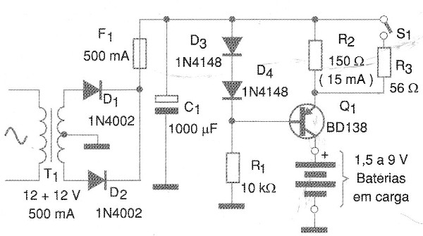
Q1 - BD138 - medium power PNP transistor
D1 and D2 - 1N4002 or equivalent - rectifier diodes
D3 and D4 - 1N4148 - general purpose diodes
Resistors:
R1 - 10 k ohms x 1/8 W
R2 - 150 ohms x 1 W
R3 - 56 ohms x 1 W
Capacitor:
C1 - 1000 uF x 25 V - electrolytic
Several:
T1 - Transformer with primary according to the local and secondary network of 12 + 12 V x 500 mA
F1 - 500 mA - fuse
S1 - 1-pole wrench x 2 positions
Printed circuit board, wires, heat radiator for transistor, solder, power cable, etc.


