
A pair of LEDs flashing in your car or in your home can lead the intruder to think about these possibilities and find another victim easier. We propose a device that has only a psychological effect, suggesting to intruders that it is an unfailing alarm.
A pair of LEDs flashing continuously on a panel reading "Super Alarm" or something like that can discourage intruders who want to steal your car or your home.
Very simple to assemble, it is a circuit that can save your assets, offsetting all the money invested, if the reader is not going to get the material in your house.
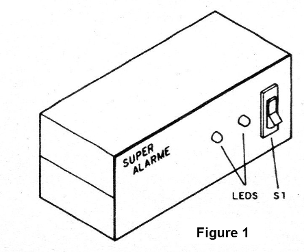
In figure 1 we show a suggestion of canister to place this circuit.
The unit can be supplied with standard batteries (in the home) or from the 12 V battery removed from any point in the system, for example with a suitable cigarette lighter connector.
HOW IT WORKS
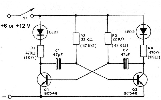
We have an astable multivibrator with two transistors that alternately drive the current, feeding two LEDs.
The frequency of this multivibrator is determined primarily by the resistors (R2 and R3) connected to the bases of the transistors and by the capacitors C1 and C2. Capacitors C1 and C2 can be decreased if the assembler wants faster blinks (10 uF or 22 uF).
For slower blinks, they can be increased (100 pF or even 220 uF). The resistors have two values in the diagram. These values are a function of the supply voltage, since the unit can operate with 6 V (4 small batteries) or 12 V (car). The values in parentheses are just the ones corresponding to the 12 V supply.
ASSEMBLY
In figure 2 we give the complete diagram of this apparatus.
The assembly carried out on a terminal strip is shown in figure 3.
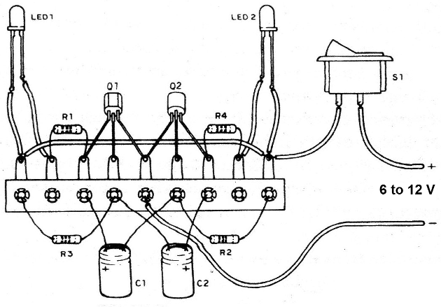
We also give the printed circuit board version, which allows the realization of a very small device.
When carrying out the assembly, take the following precautions (also with obtaining the components):
a) The original transistors are of type BC548, but equivalents like BC237, BC238, BC547 or BC549 can be used.
Note its position due to the flat part of the housing.
b) In the prototype we use a green LED (LED1) and a red LED (LED2). The LEDs may be red or otherwise colored if you prefer.
Important in connecting and following the polarity given by the shorter terminal or flat part of the enclosure.
If there is a reversal, it will not turn on.
c) The resistors can be 1/8 W or 1/4 W and the values depend on the power used. See the values in the material list.
d) The capacitors C1 and C2 were originally 47 uF x 12 V, but higher voltage types and different values may be used depending on the speed desired for the blinks.
e) The power connection must be made with different colored wires: red = positive wire and black = negative wire.
The positive switch passes a general switch (S) to switch the appliance on and off. For 6 V power, use a holder of 4 small batteries. Upon completion of the assembly, the operating test is very simple.
TEST AND USE
Connect the appliance to a 6 V or 12 V power supply according to its version, observing the polarity.
The LEDs should flash alternately.
If you want to change the speed, change the values of C1 and C2.
If the unit does not work, see if one of the LEDs (or both) is not inverted, or the transistors are.
Install the device in the box and connect it to the car or source (batteries).
Semiconductors:
Q1, Q2 - BC548 or equivalent - NPN transistors
LED1 - Green LED, common
LED2 - Red LED, common
Capacitors:
C1, C2 - 47 nF x 12 V - electrolytic capacitors
Resistors:
(Yellow, violet, brown) or 1 k x 1/8 W (12 V) - resistors (brown, black, red)
Resistors (red, red, orange) or 47 k x 1/8 W (12 V) - resistors (yellow, violet, orange)
Several:
S1 – On-Off switch
Terminal block or printed circuit board, mounting box, wires, solder, etc.


