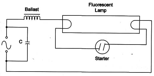
In traditional installations, fluorescent lamps use a starter and a balast in a configuration, such as shown in Figure 1.

The starter acts as an automatic switch cIosing and opening the inductive circuit to produce high-voltage spikes.
These spikes are necessary to ionize the gas inside the quorescent Iamp.
As Iong as the gas is ionized, the Iamp becomes conductive, and Iight is emitted.
When the Iamp is conductive, after the initiaI process, the starter is now inactive.
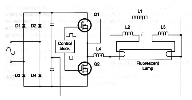
With eIectronics, the traditional ballast is replaced by high-voltage and high-frequency circuits that use modern components Iike power FETs and ICs (Figure 2).

This circuit is reaIIy a high-frequency inverter operating directly from the AC power Iine. The AC is rectified and used to drive ahigh-power oscillator stage with a transformer. The load of the transformer is the quorescent Iamp.
The difference between this circuit and the traditional configuration is the efficiency (more electric energy can be converted into Iight), and the oscillations in the AC power-Iine voltage don't influence or interfere in the circuit operation.
But, the basic difference, for the reader to observe, is the presence of an electronic circuit inside it.
When working with electronic baIIast, watch out for EMI. The high-frequency operation of some circuits requires special care to avoid interference with nearby radio equipment.
The basic procedures include the use of filters and grounding.


