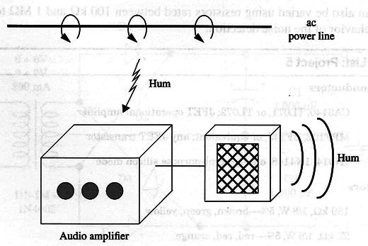
If you touch a bare wire that is plugged to the input of any audio amplifier, you can hear this hum.
The sound comes from the 60 Hz signal picked up by your body and amplified by the circuit. To avoid the hum, the circuits must be shielded. But, in some cases, even this procedure is not enough to block the incoming 60 Hz signals.
The hum can enter via an improper filtering circuit of a power supply, low-signal circuits, or even when you use a long cable to plug a microphone into the circuit or to transfer signals from one piece of equipment to another.
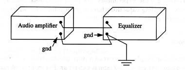
A few microvolts of difference in the ground potential levels of two devices is enough to induce hum. For the ITC researcher or those who are trying to find the best combination of audio equipment for making these experiments, the noise can become a serious problem.
As Fig. 2 shows, two devices can be connected to a common ground to avoid hum.

How It Works
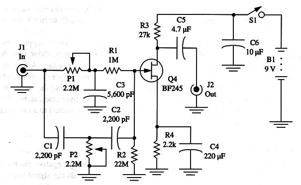
The circuit is formed by an FET amplifier stage with strong negative feedback made by a resonant twin-T circuit. The feedback circuit feeds the signal back to the output only if its frequency is 60 Hz. This means that the gain of the circuit is reduced for 60 Hz signals but kept normal with other signals.
The potentiometer is used to tune the circuit to the exact frequency to be rejected 60 Hz, or 50 Hz if this is the frequency of your ac power line.
Notice that this circuit has a high-impedance input and can’t be used directly with transducers such as loudspeakers or earphones.
The circuit also provides a gain to the input signal. Therefore, it can be used also as a preamplifier for microphones when installed between the amplifier and the microphone or other audio sources.
Assembly
The circuit of the Hum Filter is shown in Fig. 3.

The circuit can be mounted on a small printed circuit board and installed in a metallic or plastic box. Metallic boxes are preferred, as they can act as a shield to prevent the circuit from picking up external noise. Jacks are used to plug the circuit to the audio source and to the input of an amplifier.
Any NPN general-purpose JFET transistor can be used in the project. Types such as the BF245, MPF102, or any other can be used. Note that the transistor, depending on the type, may have different terminal placements. The patterns shown in the figure are for the BF245.
The circuit is powered from a 9 V battery. As the current drain is very low, the battery life can be extended to several weeks. Keep the wires short to avoid hum after the amplification stage!
Using the Circuit
Plug the output of the tape recorder into the input of the filter if the tape is found to have a high level of hum. Other audio sources with high hum levels can be plugged into the input, including sensors, microphones, etc.
Adjust P1 to block the hum. If you can not find the correct setting when adjusting these components, alter the values of C1, C2, and C3. Values 50% higher or lower than the suggested ones can be used experimentally. The values of the capacitors must maintain the same ratio as the original values.
This means that if you multiply by 2 the value of C1, you must also double the values of C2 and C3 when performing these experiments. We must remember that many electronic components, including capacitors, have high tolerances for which we must compensate in some cases.
Suggestions
- This circuit can be placed between a microphone and a tape recorder input if you are using long cables and hum is picked up. For many applications, such as when recording with a long microphone cable, this filter can be quite helpful.
- Replace R8 with resistors rated between 15 and 47 k ohm if distortion appears in the sounds.
Use other values for C3, C4 (0.1 µF), and C2 (0.22 µF) if you intend to use the device in a 50 Hz power line.
Semiconductors
Q1 BF245 or equivalent, JFET
Resistors
R1 - 1 M ohm, 1/8 W, 5% - brown, black, green
R2 - 22 M ohm, 1/8 W, 5% - red, red, green
R3 -27 k ohm, 1/8 W, 5% - red, violet, orange
R4 - 2.2 k ohm, 1/8 W, 5% - red, red, red
Capacitors
C1, C2 - 2,200 pF, ceramic or metal film
C3 - 5,600 pF, ceramic or metal film
C4 -220 µF/ 12 WVdc, electrolytic
C5 - 4.7 µF, 12 WVdc, electrolytic
C6 10 µF, 12 WVdc, electrolytic
Miscellaneous
P1 - 2.2 M ohm - potentiometer
S1 - SPST, toggle or slide switch
B1- 9 V battery
J1, J2 - Jack (see text)
Printed circuit board, plastic box, battery clip, wires, shielded cable, solder, plastic knobs, etc.


