
The proposed alarm system is formed by a transmitter and a receiver interconnected by means of a wire passing through the sensing elements.
The low frequency signals generated by the transmitter, which are actually short pulses, keep the receiver energized in such a way which the relay is deactivated.
If there is an interruption on the signal path, the receiver circuit detects the absence of the pulses and triggers the relay.
The great advantage of this system is the sensitivity of the receiver which allows to use the earth to close the circuit and, in addition, a very long cable between the transmitter and the receiver. This second fact facilitates the use of the alarm in the protection of large environments.
The transmitter and receiver can be powered by independent sources, provided that with the same voltage, the characteristics of the relay determine the type of warning device that can be triggered.
HOW IT WORKS
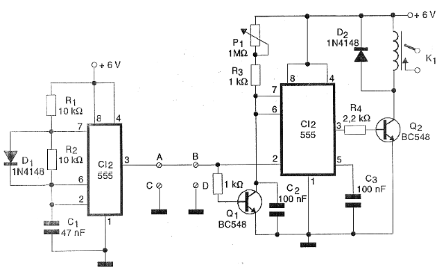
The transmitter is formed by an integrated circuit 555 (CI-1) which operates as an astable where the operating frequency is determined by R1, R2 and C1. The diode works to obtain a mark-space relation more appropriate for the operation of the system.
The capacitor is charged by R1 and discharged by R2 in this configuration.
The pulses generated by this oscillator are applied directly to the line where the sensors are interleaved. The line itself is a sensor, since if it is interrupted it causes the alarm to sound.
The receiver basically consists of an integrated circuit 555 connected as a non-pulse detector. In this circuit, pulses of a certain duration and interval, determined by the P1 setting, must be applied so that the output remains at the low level.
The time constant given by P1, R3 and C2 allows detecting when a pulse is missing in the train to be applied to the circuit. When this occurs, the output of 555 goes to high level, thus saturating transistor Q2.
The collector load of the transistor Q2 is the relay which controls the external warning circuit.
The supply voltage of the circuit can be changed in the range of 5 to 12 volts depending only on the characteristics of the relay used.
ASSEMBLY
In figure 1 we have the complete diagram of the apparatus.
The arrangement of the components for the transmitter and the receiver on two printed circuit boards is shown in Figure 2.

Integrated circuits for safety can be assembled in DIL sockets. The relay, if it is of a different type than the one indicated, may have a different base shape, thus requiring a change in the design of the printed circuit board.
The resistors are all 1/8W with 5% or more tolerance and the transistors admit an equivalent. The diodes also support equivalents such as 1N914, 1N4002, etc.
The capacitors are all ceramic or polyester.
In Figure 3, we show a power supply which works both the receiver and the transmitter.

The transformer must have primary winding according to the power supply and secondary 9 + 9 V with at least 300 mA. If the receiver is too far from the transmitter, two separate sources must be used.
The source integrated circuit does not need to have with a heat radiator since the alarm consumption is low and only slightly higher when the relay is energized.
Any type of wire can be used to connect the transmitter to the receiver. Grounding is important to ensure proper operation of the system and can be done on any large object in contact with the earth, on a metal bar buried as well as on the neutral pole of the outlet.
The maximum length between stations is not critical and can exceed 1 000 meters. Changes to component values, specifically C1 and C2, may be required if erratic operation occurs with very long wire lengths.
TEST AND USE
Interconnect the stations and set P1 so that the relay is close to the trigger point. This is the only setting needed to get the alarm working. Just check if undoing the interconnections between the two circuits occurs the trigger.
In order to obtain the relay shutdown in case of interruption of the link between the receiver and the transmitter, the output stage which drives the relay can be modified as shown in Figure 4.

This change allows you to use the circuit in other equally interesting applications.
If the circuit tends to trigger by buzzing, which can occur with very long wires between the receiver and the transmitter, shielded wires can be used between two sensor placement points. The meshes of these wires should be grounded.
In Figure 5, we show how a long fence can be protected with several sensor points.

Semiconductors:
CI-1, CI-2 - 555 - integrated circuit
Q1, Q2 - BC548 or equivalent - general purpose NPN transistors
D1, D2 - 1N4148 or equivalent - general purpose diodes
Resistors: (1 / 8 W, 5%)
R1, R2 - 10k ohms
R3 - 1k ohms
R4 - 2.2 k ohms
P1 - 1 M ohms - trimpot
Capacitors:
C1 - 47 nF - ceramic or polyester
C2, C3-100 nF - ceramics or polyester
Miscellaneous:
K1 - 6V relay - G1RC1 or equivalent - see text
Printed circuit board, material for power supply, sensors and cable, mounting box, wires, welding, etc.


