Translated into English by Patricia Lima Carlos
You hide the crazy dripping in a friend's room who wants to sleep.
Ready! The trap is set. He/she only needs to turn off the lights which the dripping comes into action automatically. Imitating a well-paced leak, it will disturb your friend who will surely turn on the lights to search for it.
But, that does not help! When the lights are turned on it will stop automatically, getting very hard to find its location.
Have fun with this automatic assembly which works with 4 batteries and that, by low consumption, can perfectly stay on all night long (to torment your victim).
This dripping assembly does not require special knowledge or components, and can be easily made in both the terminal bridge and printed board versions.
How it works
Analyzing each block makes it easier to understand how the crazy dripping works.
The first block consists of a slow oscillator - an astable multivibrator which is controlled by an LDR. The transistors of this multivibrator (Q1 and Q2) alternately drive the current giving the beat to the leak dripping.
When the LDR is lit, the multivibrator is inhibited, not working.
When the LDR receives light, the multivibrator starts operating.
The pulses of the multivibrator are used to control a double T damped oscillator based on a transistor (Q3).
The double T oscillator is set at P1 to produce a damped oscillation, which in terms of sound translates into a resonant effect such as dripping of a drop of water on a glass or a can. (Figure 1)
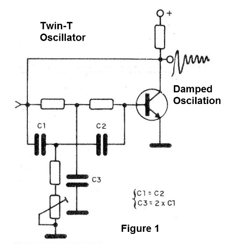
As readers will realize, the imitation is perfect, and for changes of effect just change C3, C4 and C5. However, in this change C3 and C4 must be maintained with the same value, and C5 with double. For example, if you change C3 to 4n7 (getting a lower pitch sound), C4 should also go to 4n7 and C5 to 10nF which is the closest double value.
The damped oscillation produced by the Twin T is brought to an amplifier stage with two transistors.
The volume depends on the power consumption. As it is not interesting to have high volume in this circuit, because the device would be located easily and there would be no realism in the imitation of the dripping (which is usually low), the power is small, basically determined by R11.
At the indicated value of R11, the standby current consumption will be approximately 3 mA, which means a very long battery life.
The loudspeaker, the final assembly link, can be a 10cm miniature type with 4 or 8 ohm.
Assembly
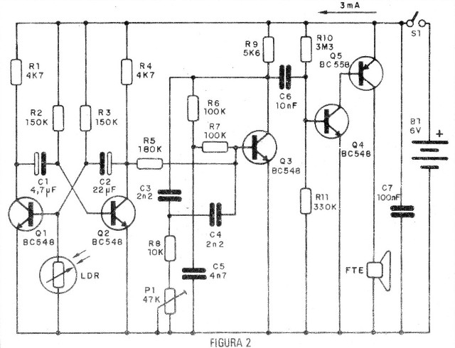
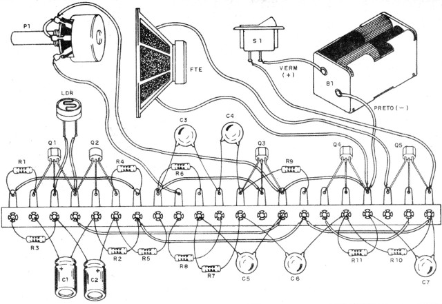
In Figure 2, we have the complete dripping circuit and our suggestion of a terminal strip assembly is shown in Figure 3.
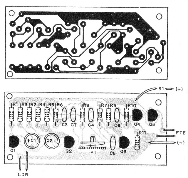
For those who have the possibility to make the assembly on a printed circuit board, we give its drawing in Figure 4.
Of course, the box in which the device is to be installed must have dimensions depending on the chosen version.
In addition to the normal care about the polarity of the components, we have some recommendations to make for their arrangement and obtaining.
a) The transistors can be replaced by equivalents, without problems. Be careful not to exchange Q5 that is PNP with the others.
b) The LDR1 is of the ordinary round type, being able to be used of old televisions which have automatic control of brightness. This LDR must be built to receive ambient light. A hole in the box should be made for this and the LDR will be installed under that hole.
c) The electrolytic capacitors must have a working voltage of at least 6 V.
d) The resistors are all 1/8 or 1 / 4W, depending on the availability of the assemblers, and P1 can either be a trimpot or a potentiometer. With the potentiometer we have an easier immediate adjustment of the sound that the dripping will produce.
e) The other capacitors can be ceramic or polyester.
Upon completion of the assembly, the operating test is simple.
Test and Use
Insert the batteries into the holder.
Turn S1 on. If the unit tends to oscillate, set P1 until it stops. From time to time (2 to 5 seconds) the appliance should click.
Then adjust P1, so that this click sounds like a drip of water hitting a metal or glass object.
To perform the test, the LDR must be covered, because when receiving light the oscillator must stop.
Experiment the LDR's acting by uncovering it.
Once the operation is tested, we only need to install it in a box.
Remember that the LDR must be exposed to ambient light, having a hole in the box for this purpose.
To use the appliance proceed as follows:
a) Turn the unit on and set P1 to the desired sound.
b) Hide it in the victim's room in a position where the LDR receives the light from the lamp which illuminates it.
Turn on the light so that the appliance is "inhibited".
c) Wait to see what happens!
When the "victim" turns off the light, the dripping will begin to produce its sound. When this "victim" decides to turn on the lights to look for it, it will stop!
The "victim" will go crazy!
Be careful not to get the device thrown on your head when people find out who did the prank!
Q1, Q2, Q3, Q4 - BC548 or equivalent - NPN transistors
Q5 - 80558 or equivalent - PNP transistor
P1 - 47k - trimpot or potentiometer
LDR - common round LDR
S1 - Single switch
B1 - 6 V - 4 small batteries
R1, R4 - 4k7 - resistors (yellow, violet, red)
R2, R3 - 150k - resistors (brown, green, yellow)
R5 - 180 k - resistor (brown, gray, yellow)
R6, R7 - 100k resistors (brown, black, yellow)
R8 - 10 k - resistor (brown, black, orange)
R9 - 5k6 - resistor (green, blue, red)
R10 - 3M3 - resistor (orange, orange, green)
R11 - 330 k - resistor (orange, orange, yellow)
C1 - 4.7 uF - electrolytic capacitor
C2 - 22 uF - electrolytic capacitor
C3, C4 - 2n2 (222) - ceramic capacitors
C5 - 4n7 (472) - ceramic capacitor
C6-10 nF (103) - ceramic capacitor
C7 - 100 nF (104) - ceramic capacitor
FTE - small speaker
Miscellaneous: terminal bridge or printed circuit board, assembly box, 4 battery holder, wires, welding, etc.