The recommended SCR is rated to 4 A but, for a safe operation, do not use the control with greater than 200 W loads (incandescent lamps or heaters-do not use the device with inductive loads or fluorescent lamps).
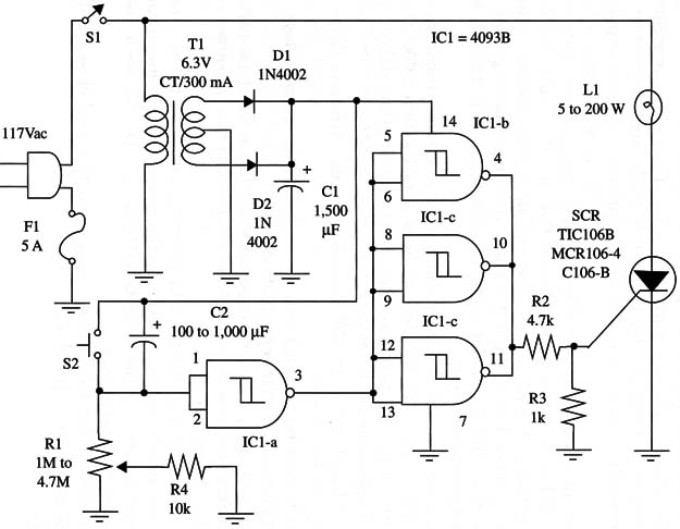
The circuit works as follows. When S1 is closed, the power supply is on, and C2 begins to charge Via R1 and R2. At the same time, a high level is applied to the IC1-a input, giving a low output in this gate and, consequently, a high output level at ICl-b, c, and d outputs. The high output level triggers on the SCR, powering up the incandescent lamp.
When Vp is reached at the ICl-a input, its output goes high and, at the same time, IC 1-b, c, and d outputs go 1oW, turning off the SCR and also the incandescent lamp.
To set a new time delay, you have only to press S2 and discharge S2. Time delays of up to 30 minutes can be obtained with a 1,000 µF capacitor and a 4.7 M ohm potentiometer. To reduce the time delays, you can use a low-value capacitor for C2.
Observe that the transformer is on when S1 is closed, even when the lamp is off, but power consumption is low in that condition.
A schematic diagram of the Incandescent Lamp Timer is shown in Fig. 1.

The SCR must be mounted on a heatsink. To adjust time delays, R1 can be replaced by a trimmer potentiometer.
Positions of the polarized components (diodes, electrolytic capacitors, and SCR) must be correct. All the components can be housed in a plastic box, except the lamp.
Remember that this circuit is in direct contact with the ac power line. Wiring should be carefully checked to make sure that metal parts do not contact wires or components to the ac line. Do not use a metal box to house the components.
In use, first adjust R1 to the desired time delay and close S1. The lamp will glow during the adjusted time delay. To set a new time delay, press S2.
IC1 - 4093 CMOS integrated circuit
SCR1 - TIC106-B or equivalent silicon thyristor (200 V, 4 A)
D1, D2 - 1N4002 or equivalent 50 V, 1 A silicon diodes
T1 - 6/3 V, 300 mA to 500 mA secondary, 117 Vac primary, CT transformer or equivalent
S1 - SPST toggle or slide switch
S2 - SPST momentary switch
F1 5 A fuse and holder
L1 - 5-200 W incandescent lamp (see text)
R1 -1,000,000 ohm to 4,700,000 ohm - potentiometer
R2 - 4,700 ohm, 1/4 W, 5% resistor
R3 - 1,000 ohm, 1/4 W, 5% resistor
R4 - 10,000 ohm, 1/4 W, 5% resistor
C1 -1,500 µF, 15 WVDC electrolytic capacitor
C2 -100 µF to 1,000 µF, 12 WVDC electrolytic capacitor


