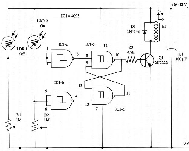
The circuit can be powered from 6 V or 12 V power supplies, depending on the relay you have in hand to the project.
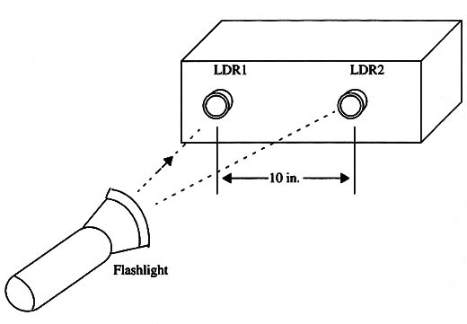
The sensor cells should not be placed in a position where they are excessively illuminated, and they should be separated from one another by a minimum distance of 10 inches. This separation is needed to keep the flashlight from triggering both cells at the same time.
Loads up to 1 A can be controlled with a mini DPDT 1 A relay (Radio Shack 275-249), and you can also control powerful loads by replacing the original relay with a 10 A SPDT 10 A relay (Radio Shack 275-248).
The sensors are common CdS photocells or LDRs with diameters ranging from 1/4 to 1 inch. Any type is suitable for this project.
The power supply depends on the intended application. You can use AA cells or a battery for a portable use, or a 117 Vac or 12 Vdc power-supply for 500 mA or more.
A schematic diagram of the device is shown in Fig. 1.

Each photocell is housed in an opaque cardboard tube. Directional action is given by a convergent lens placed in front of each LDR.
The device is housed in a plastic box. Dimensions of this box are suggested in Fig. 2.

The LDRs should be separated by 10 inches or more.
Sensitivity adjustments are made by R1 and R2. You can use common potentiometers or trimmer potentiometers on the board. The load is connected as shown in the figure.
Take care with the load’s connections to avoid shock hazards, as the circuit is powered from the ac power line.
Operation is very easy. Place the remote control and the flashlight in the normal operation position within the normal ambient illumination. Adjust R1 and R2 to turn the relay on and off with short-durationflashes.
101 4093 CMOS integrated circuit
Q1 2N2222 NPN general purpose silicon transistor
D1 1N4148 general purpose silicon diode
K1 6 V or 12 V relay (see text)
LDR1, LDR2 CdS photocell (see text), Radio Shack 276-1657 or equivalent
R1, R2 1,000,0002 potentiometer or trimmer potR3 4,700 (2, 1/4 W, 5% resistorCl 100 µF, 16 WVDC electrolytic capacitor


