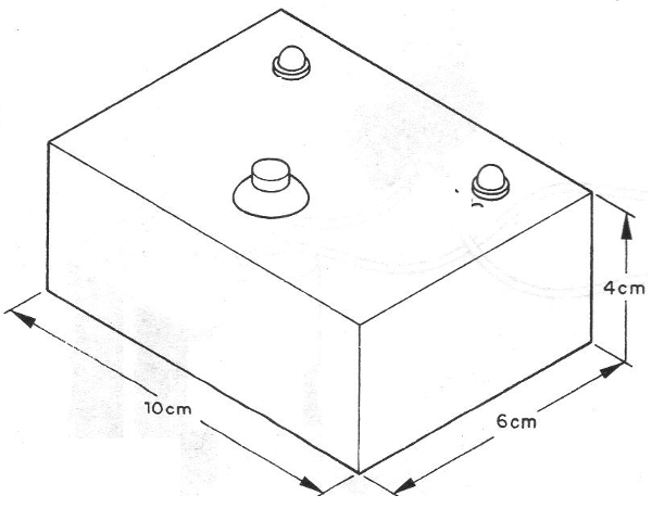
You push a button, and when you release it only one of two LEDs stays on, indicating the result of the draw (figure 1).

You can use this device to solve important "litigation" issues such as who will pay the restaurant bill, or pay out at a football match.
HOW IT WORKS
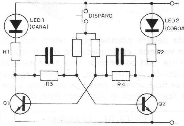
The operation of this electronic game has no secrets whatsoever. It is a multivibrator that can operate as well as astable or as bistable, as shown in figure 2.

When you push the S1 pressure switch, the multivibrator acts as a steady state, causing the two transistors to quickly switch.
By releasing the pressure switch, the multivibrator becomes a bistable one in which only one of the transistors is in conduction, lighting the corresponding LED.
As the driving change is very fast, we can not see this, so when we release the switch we can not predict which of the LEDs will be lit, which means that we can not influence the draw.
The circuit is powered with a 6 V voltage coming from 4 small batteries, or if the reader prefers, from a source.
ASSEMBLY
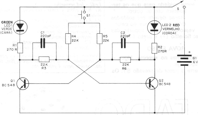
In figure 3 we give the complete circuit of the face or electronic crown with all the components represented by their symbols and their values.

If the reader is new, we recommend familiarizing yourself with the symbolism used in this type of diagram.
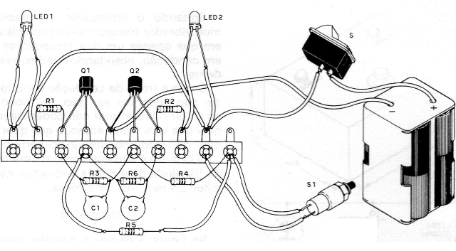
In figure 4 we give the printed circuit board assembly.

In figure 5 we have the bridged version of terminals.

The care that must be taken with this assembly are as follows:
a) Observe the position of the transistors by reference to their flattened part. Be quick in your welding.
b) Observe the position of the LEDs with reference to the flattened part of its housing.
c) The values of the resistors are given by their colored rings. When assembling a bridge, take care that the terminals do not touch one another.
d) Capacitors must be welded quickly, as they are sensitive to heat.
e) Check the polarity of the battery holder: red (+) and black (-) wire.
TEST AND USE
Insert the batteries into the cradle. Turn on the main switch S. Press the pressure switch S1. The LEDs should light up brightly (they are actually blinking too fast, and the view can not keep up).
By releasing the switch, an LED should only be accessible, being both green (head) and red (tail).
Q1, Q2 - BC548 or equivalent - transistors
LED1 - Green LED
LED2 - Red LED
R1, R2, - 270 R x 1/8 W- resistors (red, violet, brown)
R3, R4, R5 and R6 - 22k x 1/8 W- resistors (red, red, orange)
S1 – push button
S - single switch
C1, C2 - 220 pF - ceramic capacitor
B1 - 6 V battery - 4 small batteries
Miscellaneous: printed circuit board or terminal strip, box for mounting, wires, soldering, cell holder, etc.