The CMOS integrated circuits are extremely sensitive to voltage surges, operating in the narrow range from 3 to 18V and even a simple static charge accumulated in the hands of those who handle them can mean their end. On the other hand, neon lamps need at least 70 volts to light and are typical devices that operate with high voltage.
Of course, a combination of the two seems impossible, but that is not what we are going to demonstrate. Using as a driver a common transistor that supports the voltage of the lamps and this is not difficult, because the current in a neon lamp is extremely low, we can interface the output of CMOS circuits like the 4017, 4093 and others with a neon lamp and excite it !
The following applications show how this can be done.
THE POWER SOURCE
To power the high voltage sector of the circuit that makes use of the neon lamp there are two options.
One of them (which may seem less convenient) is to use 9 to 10 common 9 V batteries. This solution, however, can be interesting since, the consumption of a neon lamp is of the order of microamperes and its battery power means practically anything. The durability of the battery pack will therefore be practically the same as they would have when stored. Of course we are considering a set of some lamps only .
The other possibility is the use of a source of 80 to 90 volts of low current as shown in figure 1.
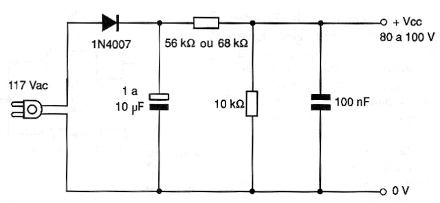
The most interesting would be to have an isolated source of the power network, since an accidental touch at any point in the circuit, besides the danger of shock can mean the application of high voltage in the component CMOS that would not resist this.
DIRECT EXCITATION
A first circuit that can be used to excite a neon lamp is what makes the direct excitation and which is shown in figure 2.
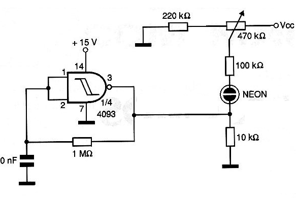
This is a flasher or simply a logic gate that drives a neon lamp. In this circuit the firing point of the neon lamp must be set in the 100 k ohm trimpot very carefully. The trimpot will be adjusted so that the voltage applied to the lamp is close to the trigger point. This voltage will be increased slightly when the output of the integrated CMOS is low, when the lamp lights up. The voltage divider, formed by the resistors in series with the neon lamp, however, ensures that the voltage at the CMOS output does not exceed 1/10 of the voltage set at the trimpot slider.
For application as a blinker the capacitor and resistor R1 determine the operating frequency of the circuit. The CMOS should be powered with a voltage between 12 and 15 volt for greater efficiency in the firing as this is the difference between the trigger threshold and the lamp trip.
Note that this setting requires that the neon lamp power is supplied with a negative voltage.
EXCITATION OF NEON BY 4017
The same technique used in the previous circuit allows the realization of sequential projects with neon lamp where the excitation is done directly by an integrated circuit 4017. This application is shown in figure 3.
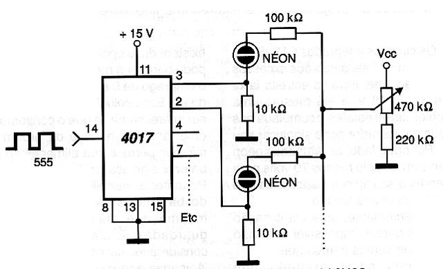
We show only the excitation of two lamps and the following steps are repeated with the same configuration. An important care in this circuit is that the trimpot setting for the tripping voltage requires that the used bulbs trip more or less at the same voltages. This may require that in a batch of lamps the reader selects those that work well in the circuit.
Also in this case, the supply of the integrated circuit must be relatively high since it is the voltage difference in the output that will make the drive. The voltage applied to the neon lamp circuit, as in the previous case, must be negative.
CMOS-NEON BLINKER
Our second circuit that combines two technologies (CMOS with NEON) is shown in figure 4 is a blinker that can excite a neon lamp with an active cycle of 50%.
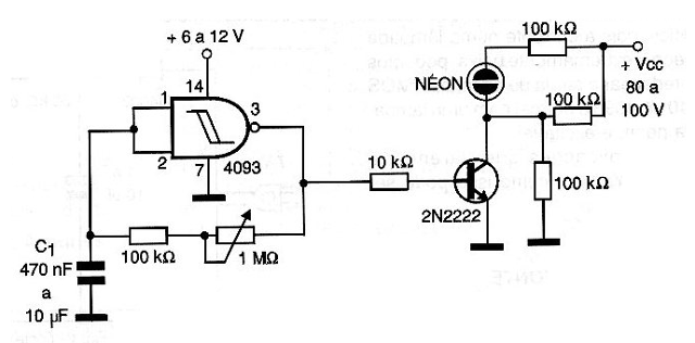
The frequency of the blinks depends basically on the capacitor C1 and is set on the trimpot P1. Values for C1 may typically be between 470 nF and 10 Â?F. The supply of the integrated circuit can be made with voltages of 5 to 12 V and the negative of the independent source of low voltage must have a point in common with the negative of the high voltage source.
To excite the neon lamp transistors such as 2N2222 or equivalent with collector voltages over 60 V can be used.
NEON SEQUENCIAL
The circuit shown in figure 5 is a variation of the previous one in which transistors are used in the trip.
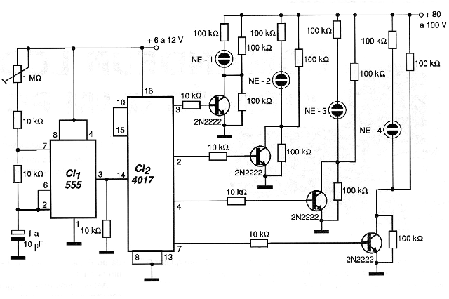
The advantage of this circuit is that the integrated CMOS does not need to be powered at a high voltage. The CMOS sector of the circuit can be powered with voltages from 6 to 12 volts without problems. The transistor used may be the 2N2222 or equivalent with a maximum collector / emitter voltage of at least 40 V.
Also note that for this circuit we do not need to adjust the firing point of the neon lamps as it does in versions that do not use the transistors for excitation.
CONCLUSION
The circuits presented in this article show that the CMOS / NEON combination is not as incompatible as milk mango as many have always believed. Interesting circuits can be made based on these interesting settings.
The reader with more imagination can create several useful applications for these circuits. We suggest that those who "discover" new applications for these circuits send them to us to publish in our edition Out of Series. The reader can win even a prize.


