
Just touching a delicate component on an object charged with static electricity can irreversibly damage it. And this is not so hard to come by: a person who walks on a carpet on a dry day can get a load that raises their potential to more than 5,000 volt easily!
In physics labs we are accustomed to seeing a simple apparatus that detects the presence of charges stored in a body which is the electroscope of sheets shown in figure 1.

However, besides this device being uncomfortable to use except in classroom demonstrations, its sensitivity is not the greatest. The electronic version we present in addition to being extremely sensitive to use electronic components, can be transported with ease and is quite simple to assemble.
Physics and electronics teachers can count on a sophisticated electroscope based on the principle of operation, sensitive by the technology but simple to assemble if they adopt this project. Using a field effect transistor as a basic element loads of small objects like pens, combs, plastic rulers and even component packaging can be detected with ease.
HOW IT WORKS
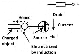
A field effect transistor has the current between its drain and the source controlled by the voltage applied to its gate. This component has an extremely high input resistance, which means a very high sensitivity to the input signals.
Thus, if an electrode that may be a metal ball or a copper ring is connected to the gate, any static charges of an approaching object can induce a voltage high enough to change the current flow between the drain and the source of the field effect transistor, as shown in figure 2.
In order to visualize then any variation of the drain current of the transistor it is sufficient to connect an indicator like for example a microammeter. In our case, what we do is connect the transistor and three more resistors to form a Wheatstone bridge. By balancing the bridge with no loads near the sensor, we can have the instrument needle in the center of the scale (the meter is zero-type in the center).
This means that depending on the polarity of the load we approach the sensor. The current may increase or decrease, unbalancing the bridge. Thus, it is enough to observe the movement of the instrument needle so that we can not only have an idea of the amount of charge stored in a body but also determine its polarity.
The power supply for the device can be made with 4 small ordinary batteries or a 9V battery. As the consumption is extremely low the battery life or battery life will be very great.
An important point to note in this project is that the transistor used as an amplifier is also extremely sensitive to high static charges. Thus, if the charged body is touched in the sensor and its charge is too high we risk the transistor to burn. This should be avoided.
ASSEMBLY
In figure 3 we have the complete diagram of the electroscope.

The arrangement of the components on a small printed circuit board is shown in figure 4.

Any junction field effect transistors (JFETs) such as BF245, MPF102, etc. can be used, since the circuit is not critical. In some cases there is even the possibility of changing the drain and source terminals without affecting the operation of the circuit. However, using an equivalent is interesting to invert the drain and the source and to experiment in which position one obtains greater sensitivity.
The indicator is a microammeter with zero in the center. The full scale current is not critical and can be between 50 uA and 500 uA without problems. The resistors are all 1/8 W or larger.
The sensor consists of a ring of coarse copper wire with a diameter of 2 to 3 cm, as shown in the figure. A metal sphere 2 to 4 cm in diameter may also be used. It is interesting to keep the hood to prevent accidental touching of an object with high load on the conductor wire which could generate a voltage high enough to cause the transistor to burn.
The box for mounting can be a small soap dish giving preference to plastic types that can be found easily in supermarkets.
TEST AND USE
Initially, turn the instrument on and set P2 so that the instrument needle goes to zero. Then cut a comb, pen or any other object that can easily electrify. Move this object closer to the sensor. The needle of the instrument must move.
If the instrument needle tends to overtake or does not move enough, repeat the experiment by adjusting the trimpot P2. This component limits the full scale current according to the sensitivity of the instrument used. Note that in some cases simply moving a loaded object within a few centimeters may already cause the needle to move.
The instrument is extremely sensitive as the reader can perceive and can be used with a telescopic antenna as a sensor, even detecting the passage of people with static charges stored in their bodies at a good distance.
In physics classes the electronic electroscope can result in a demonstration of the processes of electrification much more efficient than the traditional type of leaves, thanks to its sensitivity. If a metal ball is used as a sensor, never carry charged test cells in it, as the transistor may burn.
In physics classes the electroscope can be used in the same way as the conventional type serving to demonstrate whether or not a body has stored electrical charges and what its polarity is.
We remember that on wet days the possibility of bodies holding loads for a long time decreases. The loads "escape" into the humid air with ease discharging the bodies in a short time. An interesting experiment is to walk on a rug and then wave our hands in front of the sensor, showing how our body can accumulate large amounts of charge that can damage sensitive electronic components when we touch its terminals.
Q1 - BF245, MPF102 or equivalent - junction field effect transistor (JFET)
Resistors: (1/8W, 5%)
R1 - 1 M ohm
R2 - 10 k ohm
R3, R4-1k ohm
P1 - 10 k ohm - trimpot
P2 - 10 k ohm - potentiometer
Capacitors:
C1 - 1 pF - ceramic
Several:
X1 - sensor - see text
S1 - Single switch
B1 - 6 or 9 V - 4 batteries or battery
Printed circuit board, battery holder or battery connector, mounting box, plastic knob for potentiometer, wires, solder, etc.


